11. OPTIONS
11-4. Loop setting sensor
......
(S41959-001)
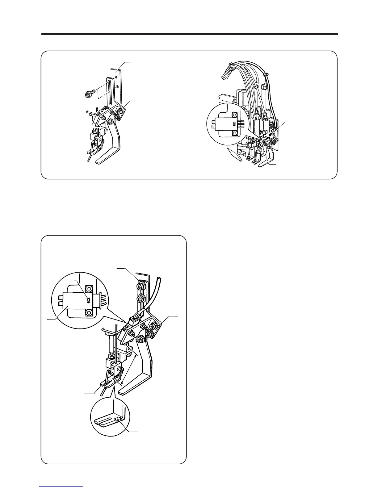
<Installation>
1. Install the loop setting sensor assembly q to slider base F w with the two bolts.
2. Insert the 3-pin connector e coming out from the control box to the loop setting sensor r.
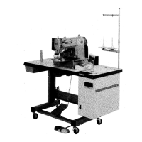
<Adjustment>
NOTE: Carry out this adjustment while loop presser foot F is raised.
― 85 ―
BAS-705
w
q
e
r
1. Loosen the bolts of loop sensor plate 1 t, loop sen
sor plate 2 y and the sensor r.
2. Move the sensor r up and down so that the sensor
light beam is aligned with the reflective surface i of
loop presser foot F u, and then find the position
where the LED of the sensor r illuminates steadily.
NOTE:
The appropriate distance between the reflective sur
face i of loop presser foot F u and the sensor r
is 40 - 45 mm.
3. After adjusting, tighten the bolts.
4. Carry out actions such as setting and removing the
belt loops and moving loop presser foot F u, and check
that the LED illuminates steadily.
r
LED
t
y
i
40〜50 mm
u