11. OPTIONS
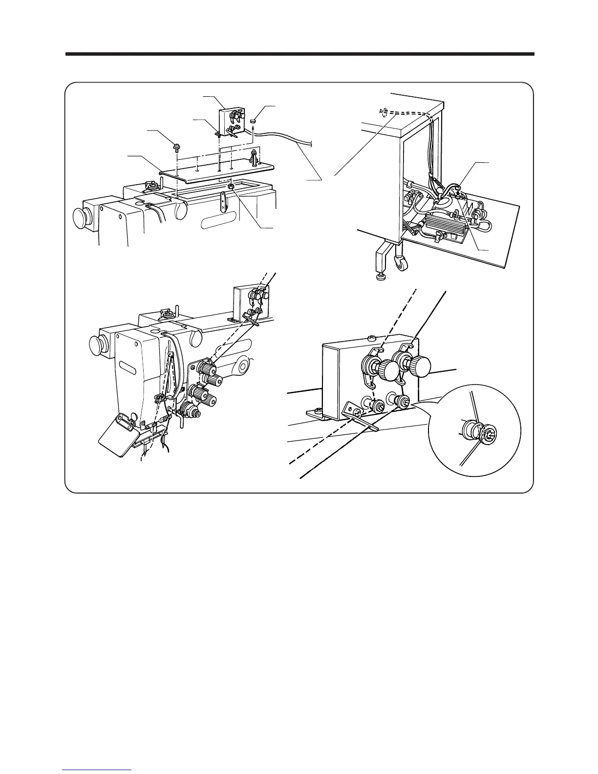
11-2. Upper thread breakage detector assembly
......
(S40520-009)
― 83 ―
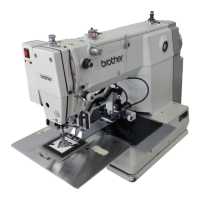
BAS-705
r
e
u
y
t
q
w
i
o
<Attachment>
1. Remove the screw q, and then remove the upper cover w.
2. Remove the upper cover cap e, and then install the thread breakage detector r to the upper cover w with
the screw t and nut y.
3. Install the upper cover w with the screw q.
4. Bind the cord u of the thread breakage detector r with the band in the same way as the other cords, and
pass it inside the control box.
5. Insert the connector i into the 16-pin connector o on the main circuit board.
<When using the upper thread breakage detector assembly>
●
Set panel DIP switch No. 1-1 to ON and then turn on the power.
<When not using the upper thread breakage detector assembly>
●
Set panel DIP switch No. 1-1 to OFF and then turn on the power.
NOTE: Refer to "8. Using the DIP switches" on page 66 for details of the panel DIP switches.