3-97
Confidential
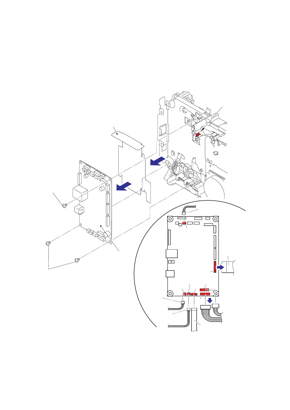
9.30 Main PCB ASSY
(1) Turn the machine upside down.
(2) Disconnect the two flat cables and the five connectors from the main PCB ASSY.
(3) Remove the three taptite cup S M3x6 SR screws.
(4) Release the hook to remove the main PCB ASSY and the main PCB sheet.
Fig. 3-86
Harness routing: Refer to “2. Registration front/rear sensor PCB ASSY”, “5. T1 clutch ASSY,
REG clutch ASSY”, “6. Paper eject sensor PCB ASSY”, “7. Main motor”,
“11. Low voltage power supply PCB ASSY”.
CN13
CN11
CN10
CN14
CN15
CN9
CN25
Main PCB ASSY
Connector
(
Internal temperature sensor
)
Main PCB sheet
Main PCB ASSY
Taptite cup S
M3x6 SR
Taptite cup S
M3x6 SR
Hook
Connector
(T1 clutch ASSY)
Connector
(LVPS
harness ASSY)
Flat cable
(main motor)
Flat cable (paper eject
sensor PCB ASSY)
Connector
(REG clutch ASSY)
 Loading...