3-66
Confidential
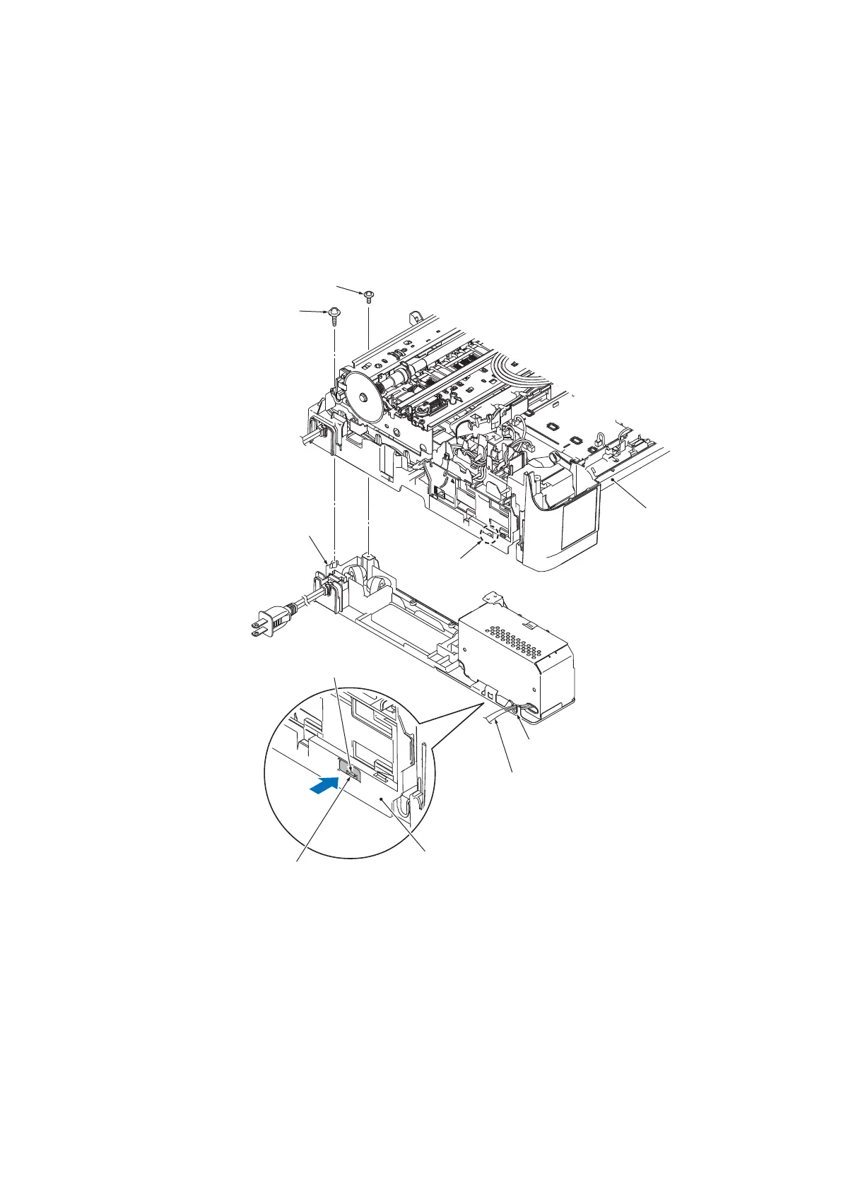
9.14 Power Supply PCB ASSY
(1) Remove the screw of the TAPTITE CUP B M3x10 and the screw of the TAPTITE CUP
S M3x6.
(2) Remove the power supply harness from the lower cover cable guide.
(3) Press the upper part of lock "x" of the power supply unit, remove it from latch "y" of the lower
cover, and take out the power supply unit from the bottom side of the lower cover, as shown
below.
Assembling Note
• Before installing the power supply unit in the lower cover, route the power supply harness
towards the U-shaped notch on the lower power supply frame (refer to the illustration above).
• After installing the power supply unit in the lower cover, make sure that the power supply unit's
lock "x" is fitted into hook "y" of the lower cover.
• After installing the power supply unit, route the power supply harness to each cable guide as
shown in Section 7-5 in this chapter.
TAPTITE CUP B M3x10
Lower cover
TAPTITE CUP S M3x6
Lower cover
Lower cover latch
Lock "x"
Power supply unit
Power supply unit's lock "x"
U-shaped notch
Power supply harness

 Loading...