VÅNTEC-1 Detector User Manual Hardware Installation for the D8 ADVANCE
M88-E01072 4 - 23
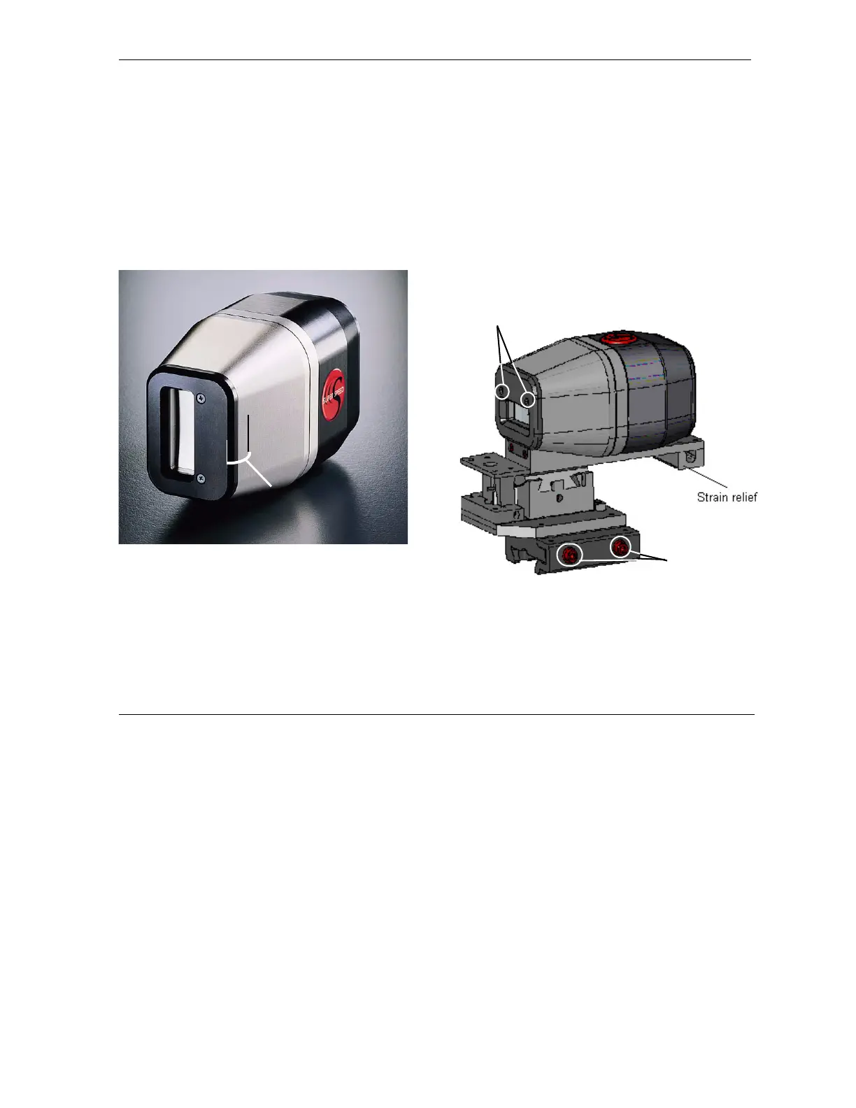
4. To confirm the proper measuring circle
radius, measure from a point at the center of
the sample stage (goniometer center) to a
point approximately 17 mm behind the
detector faceplate. This spot should be
marked on the detector head (see Figure
4.23). Use this as a reference when placing
the detector on the track.
Figure 4.23 - Connect and mount the detector
4.1 If not already attached, attach the
detector to the 2 DOF mount with the
detector mounting screws shown in Fig-
ure 4.21 and Figure 4.24.
4.2 Place the detector on the track. Slide it
down to the pinned position and tighten
the track mounting screws shown in
Figure 4.24.
5. Connect the preamplifier, HV and low volt-
age cables to the detector.
6. Adjust the cable strain relief on the detector
mount (see Figure 4.24).
Figure 4.24 - Strain relief
7. Move the 2-theta drive through the complete
range to make sure the detector moves
freely and is not restricted by the cables.
17 mm from edge of
faceplate to line
Tra ck
mounting
screws
Detector mounting
screws