Software Configuration VÅNTEC-1 Detector User Manual
6 - 12 M88-E01072
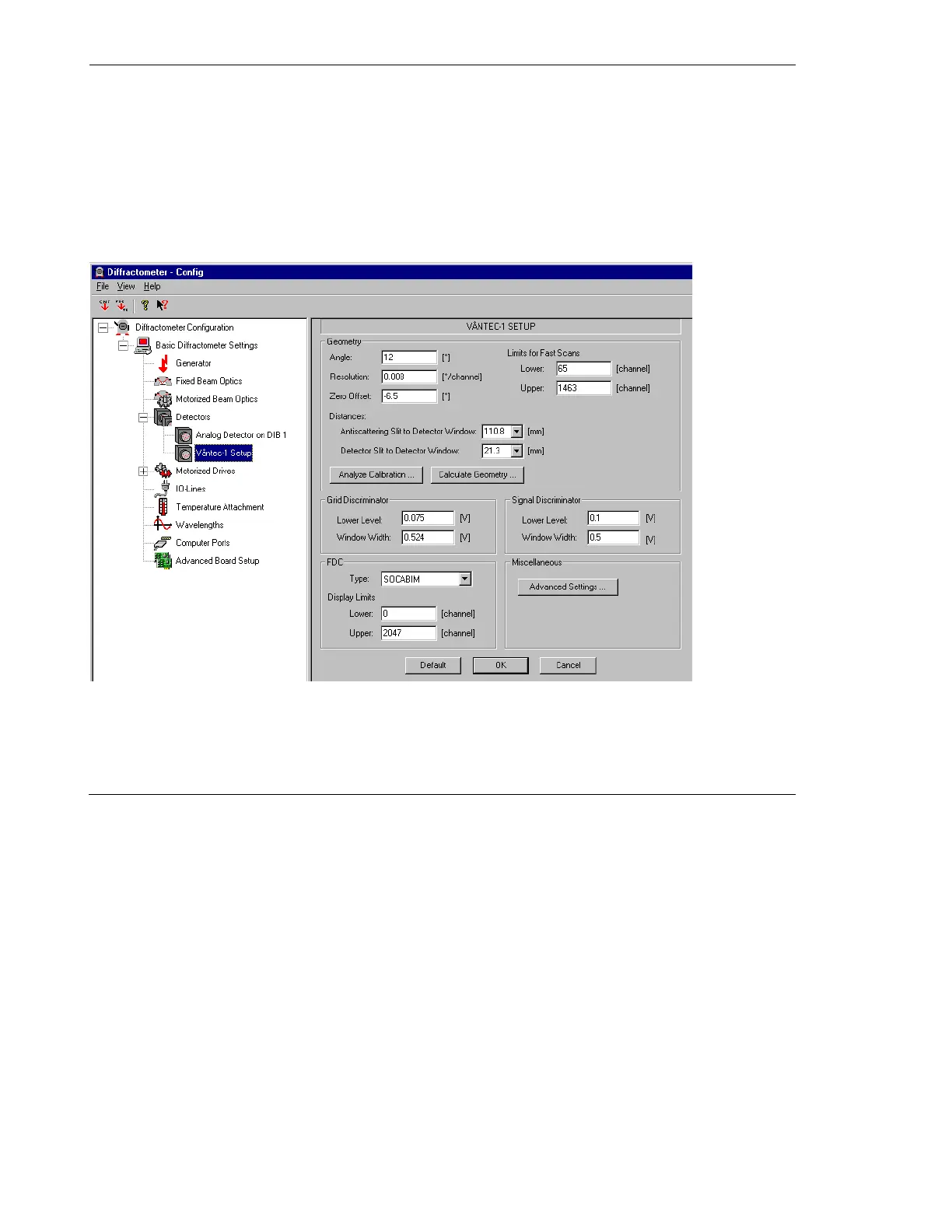
2. Select VÅNTEC-1 Setup (see Figure 6.14).
2.1 Set the Geometry Angle to 12°.
2.2 The starting values for Resolution and
Zero Offset should be 0.008 and -6.5,
respectively.
2.3 Click OK.
Figure 6.14 - VÅNTEC-1 Setup menu