VÅNTEC-1 Detector User Manual Alignment
M88-E01072 8 - 3
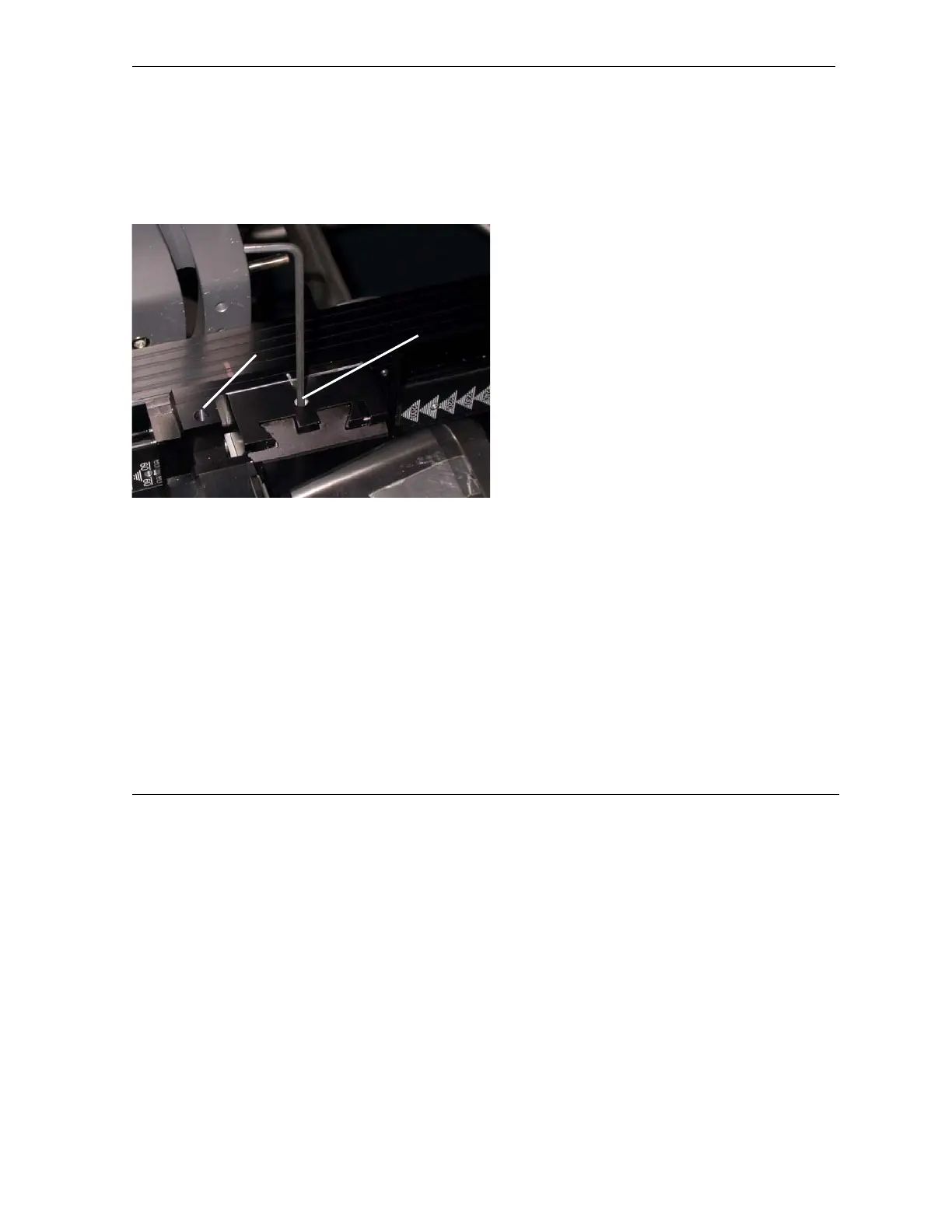
3. Adjust the yaw “Y” of the 2 DOF. The yaw
adjustment uses opposing screws. To make
an adjustment, first loosen the opposing
screw and then tighten the adjusting screw
(see Figure 8.2).
Figure 8.2 - Yaw “Y” and roll “Z” adjustments
4. Re-run the scan and compare the ratio to
the baseline scan. If the ratio increases,
continue to adjust in the direction first
attempted. If the ratio decreases, reverse
the direction of movement and repeat step 3
until the maximum ratio is achieved. Use the
ratio to check the alignment. Intensity of the
valley alone may vary.
5. Repeat step 3 and step 4 for the roll “Z” of
the 2 DOF until a ratio of 3.5 to 4.0 is
achieved. Noticeable separation can be
seen between the Kα
1
and Kα
2
peaks when
alignment is correct. Save the final scan for
future reference.
roll “Z”
yaw “Y”