22 T419S Indicator Service Manual
5 Diagnostics menu
5 Diagnostics menu
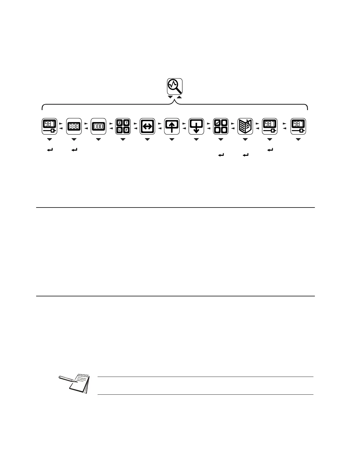
The Diagnostics menu, password 3570, is shown in Figure 5.1. Use this to test or
diagnose various functions of the indicator.
Figure 5.1 Diagnostics menu map
5.1 Scale
If a second scale is installed you can select to view values for Scale 1 through Scale 8.
Press ENTER to display the A to D counts. The value is only for diagnostic purposes.
The value should increase as weight on the scale increases and decrease as weight
decreases.
Press SELECT to toggle to a mV/V display. This is an approximate value for the mV/V
output of the combined analog load cells of the scale. If the scale is a BSQ you can only
view counts, not mV/V.
5.2 Cur.Zero
Cur.Zero This stands for current zero and represents the weight offset between the
calibration zero setting and the current zero setting due to pushbutton zero
or Auto-Zero Tracking (AZT) adjustments.
Select to view values for Scale 1 through Scale 8, if installed.
Value View the zero offset.
Clear Clear the zero offset to return the indicator to calibration zero. Choose Yes
or No.
Diag
Scale Cur.Zero Display
Buttons Ports Inputs
Outputs
Logs
Options BSQ
Counts
screen
shown
• Value
• Clear
Display
test
( toF5
stop)
Button
test
to(ZERO
stop)
• Serial1
• Serial2
• Serial3
• USB
Inputs
test
to(F5
stop)
• Output1
• Output2
• Output3
(ZERO to
stop)
• Bus 1
• Bus 2
• Card 1
• Card 2
• Print
• Clear
• Scale 1-8
• Comprss
• Tension
• Scale 1-8 • Scale 1-8
DigJbox
• T301
• ZB210
This can restore the original calibration zero point if the ENTER key is accidentally
pressed when a tank or vessel contains product that cannot be emptied.
 Loading...