78 T419S Indicator Service Manual
8 Option cards
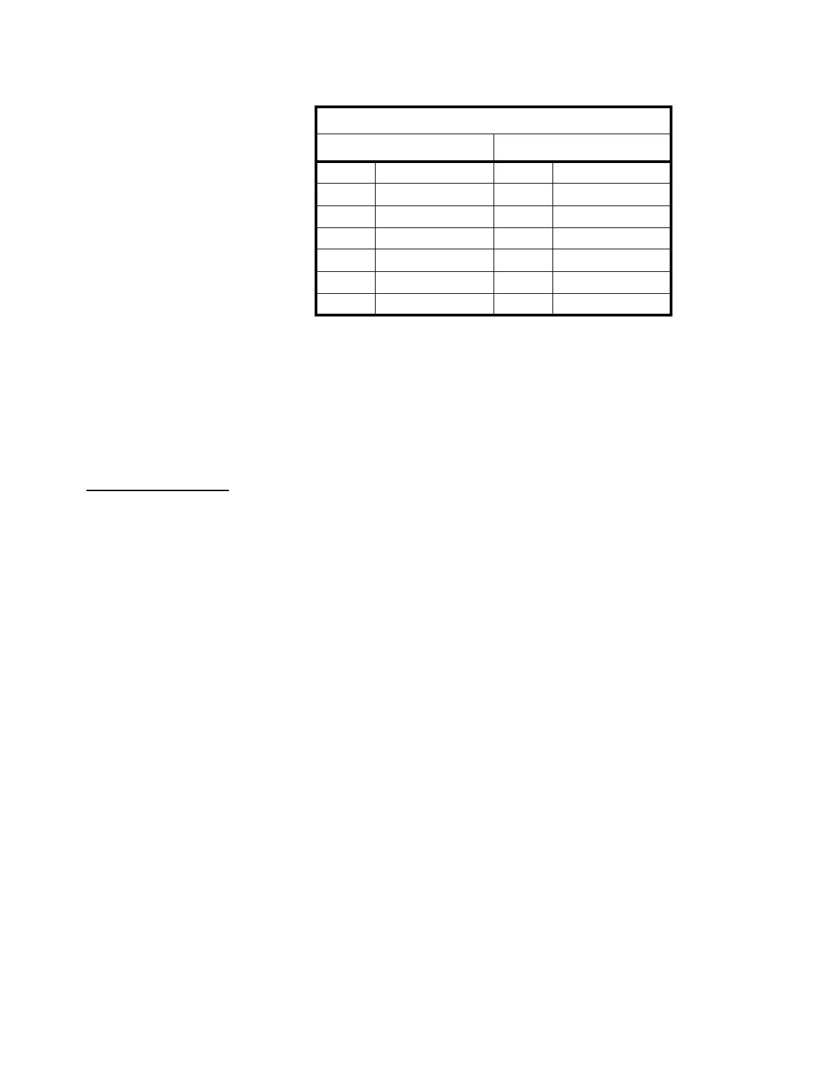
J2 (DB-9) & TB1 Pinout:
J2 and TB1 provide two connectors to the same Profibus DP interface. J2 is for
standard Profibus DP DB-9 based connector cabling and TB1 is for flying lead wiring
internal to the B-TEK Indicators enclosure.
+5V and GND are used for external bus termination if the internal S2 termination
resistors are not used.
8.6.1 S2 switch settings:
On = Termination resistors Enabled/Present (Default Position)
Off = Termination resistors Disabled/Removed
Profibus-DP
J2 DB9-Female TB1
Pin No. Signal Pin No. Signal
6 +5.0@100mA 6 +5.0 Vdc
5 Ground 2 Ground
8 -Tx/Rx 4 -Signal
3 +Tx/Rx 5 +Signal
Housing Shield 1 Shield
3RTS
 Loading...