T419S Indicator Service Manual 55
6.4 Ports menu
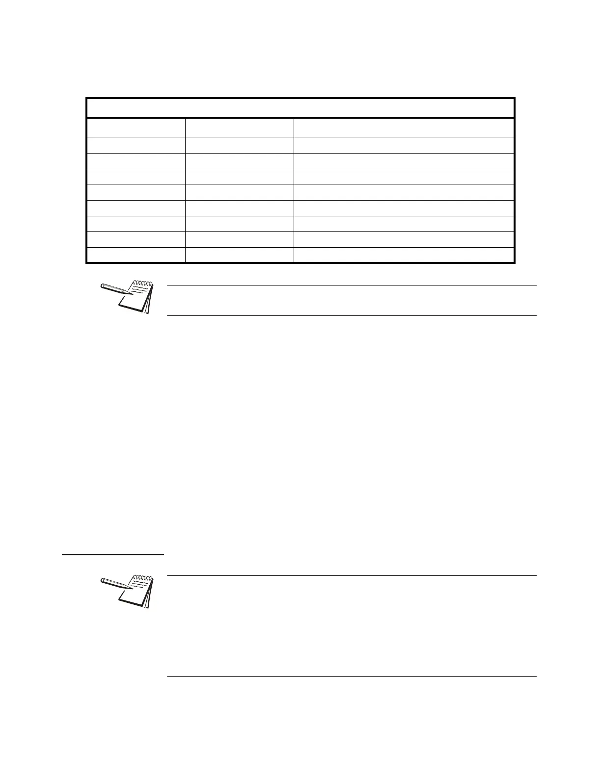
Type Below is a table showing the choices
for the Type, a description and a range
of values for that data type.
Value This stands for the network token value
to be assigned to the inbound data
memory register. Key in the value for
the network token you want from the
table above and press ENTER to
accept the displayed choice …
Repeat the process for any other
inbound memory registers you want to
configure.
Scale Choose from connected scales.
Out This stands for outbound data configuration. This menu item
is exactly like the in menu item except it is for outbound data.
Follow the same process to set up the 32 memory registers.
6.4.6 Printer
Prtr 1 You can choose to set up this printer or Prtr 2. The setup procedure is the
same.
DATA TYPE TABLE
Indicator Terminology Typical PLC Terminology Data TYPE Size
SINT8 - 1 byte CHAR / SBYTE 8 Bits (Signed Value / -127 to 127)
UNIT8 - 1 byte BYTE / UBYTE 8 Bits (Unsigned Value / 0-255)
SINT16 - 2 byte SHORT / SINT 16 Bits (Signed Value /-32767 to 32767)
UNIT16 - 2 byte WORD / UINT 16 Bits (Unsigned Value / 0 to 65535)
SINT32 - 4 byte LONG / SDINT 32 Bits (Signed Value / -2,147,483,647 to 2,147,483,647)
UNIT32 - 4 byte DWORD / UDINT 32 Bits (Unsigned Value / 0 to 4,294,967,295)
FLOAT - 4 byte REAL 32 Bits (Signed Decimal Value / 1.0E-37 to 1.0E37
STRING - 1 byte/char STRING Length Parameter setting
The Type and order of the Values selected must coincide with the configuration of the
PLC register setup. Consult with the site IT specialist.
The Printer menu is used when the indicator is interfaced with one of the printers
listed in the Brand submenu. This is necessary to ensure all the appropriate control
codes are added to the selected print format.
If either PRTR1 or PRTR2 selections are enabled then the port that is Binded may
occasionally send out a set of random characters to test for a connected printer. Be
sure to disable these settings if the indicator is not connected to one of the printer
brands listed.
 Loading...