T419S Indicator Service Manual 23
5.3 Display
5.3 Display
Use to test the segments of the display. Each digit area lights up in progression and
continues until you press ENTER.
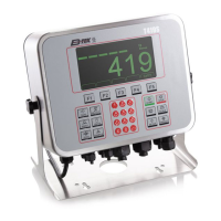
5.4 Buttons
Use to test the keys. When you begin the test, Testing is briefly displayed followed by
dashes.
Press any key to test if it is functioning and its name or value will be displayed.
Press ENTER to stop the test.
5.5 Ports
Use this to do a loopback test for serial port 1 through 3 or to perform a write/read test
on the USB port.
Serial1 to 3 When you pick a serial port to test, Testing is briefly displayed and
then Pass or Fail, depending on if the send and receive lines are
jumpered (pass) or not (fail). Add a jumper or wire between the
transmit output and receive input. On an external 9 pin connector the
transmit line is pin 2 and the receive line is pin 3.
USB Use this to test a connected USB flash drive.
Open is briefly displayed, then Write is briefly displayed, then Read is
briefly displayed, then Pass or Fail, depending on if the USB device is
working correctly or not.
If no USB device is plugged in when you begin the test, Open is briefly
displayed, then No USB is briefly displayed, then USB.
5.6 Inputs
The input test is used to verify if external switches wired to the input ports on TB2 are
functioning properly.
Follow the steps below to perform the inputs test.
1. Press SELECT …
In 000 is displayed, if no inputs are jumpered.
2. To test input 1, jumper pins 1 and 2 of the I/O connector on the indicator …
The first digit becomes 1 until the jumper is removed.
It is recommended that you insert the jumper (a paper clip works) into the external
cable connector to validate the wiring and not just the internal ports. See System
block diagram on page 123 for I/O configuration of the serial ports TB3 (Serial ports 1
& 2) and TB6 (Serial port 3).

 Loading...