Introduction
SMART MATRIX - ii -
How to Use this Manual
The manual is subdivided into 3 sections:
Section 1 – includes the connection diagrams and the electrical interface of the various system
components.
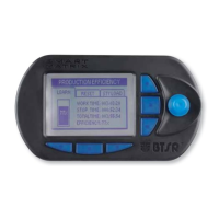
Section 2 – provides the operating instructions for a correct use of the SMART MATRIX WARP terminal
as well as the parameter configuration/programming instructions and data/errors display
facilities.
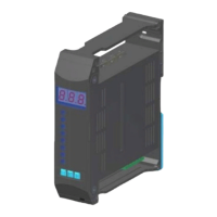
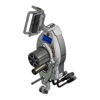
Section 3 – describes the main characteristics and performances of the various system components (IS3
sensors, TS5/TS7 sensors, SM-DIN WARP modules, etc.). Furthermore, it provides some
details to better understand the operating principles upon which the SMART MATRIX WARP
system is based (Row/Column/Bar Priority, SLOW-FAST Control Parameters, etc.).
Symbols Used
This symbol is used to point-out notes, warnings and other important information.
IS3 Within this manual, the IS3F-485 sensors used for SMART MATRIX WARP application will be
indicated with the generic wording IS3.
TS5/TS7 Within this manual, the TS5/Dttt... or TS7/Dttt… sensors as well as the last generation TS55/Dttt...
/ TS77/Dttt… sensors used for SMART MATRIX WARP application will be indicated with the
generic wording TS5/TS7.
In the program function descriptions, this symbol indicates the function
(e.g. DEVICE) within the menu item (SETUP).
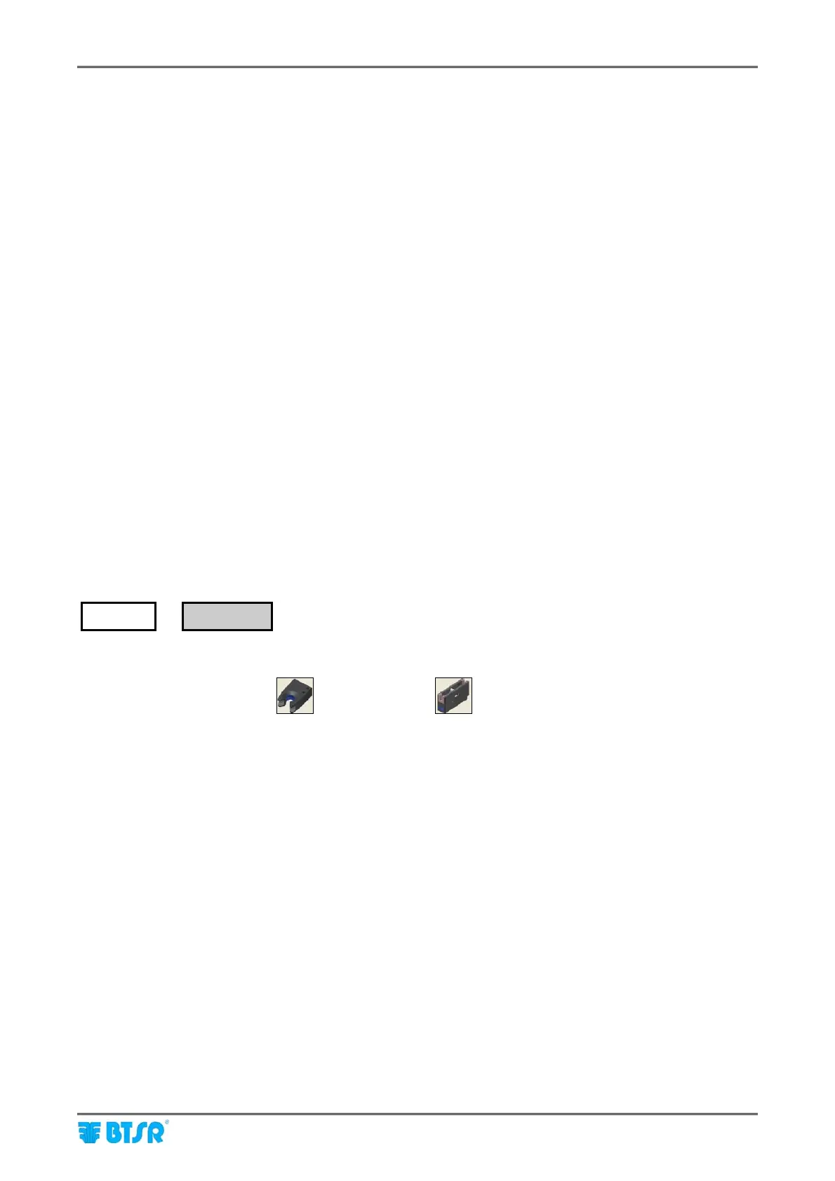
The graphic symbol of either IS3
sensor or TS5/TS7 sensor, shown on the page header, indicates
that the relevant function applies exclusively to the indicated sensor type.
SETUP
→
DEVICE