12
8175
ENGLISH
INSTALLATION
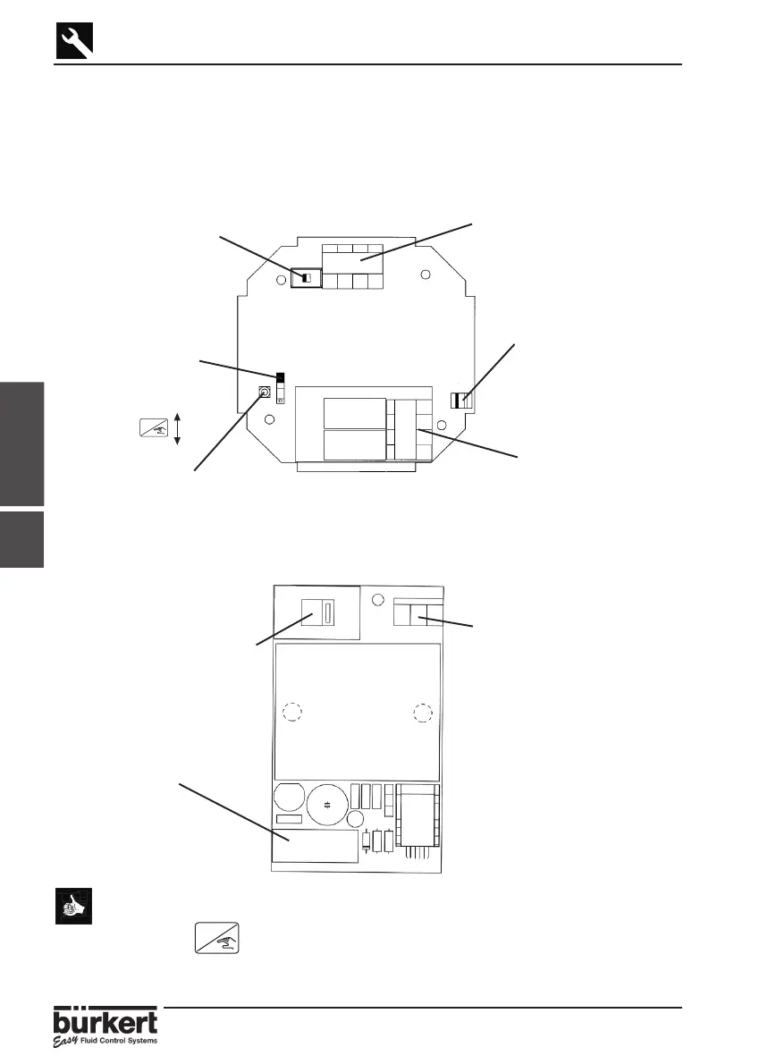
3.3 ELECTRONIC CARD IDENTIFICATION
This section allows easy identification of the features and electrical connections within
the 8175 level transmitter depending on the version.
18-32VDC ELECTRONIC CARD
115 / 230VAC ELECTRONIC CARD
(Compact version only)
● The Coax cable and PT1000 connections must be connected in all
cases to ensure the device functions correctly.
● The key can be locked to avoid accidental or unauthorised
access by placing SW1 in the up position in the diagram
above.
Terminal connections -
Connection of power supply
115/230VAC.
Power supply switch -
Changing the power supply
from 115VAC to 230VAC.
SW 2 - Sourcing or
sinking configuration.
Terminal connections -
Connection of power supply
of 18-32VDC and 4-20mA
output.
SW 1 - Locking of the
‘Enter‘ key to avoid
accidental or
unauthorised access
to the calibration and
test menus.
Sensor Coax cable
connection.
PT1000 connection.
Relay connections -
Connection of relays
1 & 2 (optional).
ENTER
Lock
Unlock
ENTER
Rel 2
Rel 1
Fuse - 315 mA T
3.3