13
8175
ENGLISH
INSTALLATION
3.4 GENERAL ELECTRICAL CONNECTION
● Use cables with a temperature limit of 80°C minimum.
● For normal operating conditions the measuring signal can be transmitted by a
simple cable of 0.75 mm
2
cross section.
● The line must not be installed in combination with carrying lines with a higher
voltage or frequency.
● If a combined installation cannot be avoided, a minimum space of 30 cm (1 ft)
or shielded cables should be adopted.
● When using shielded cables observe faultless grounding of the shield.
● For EMC purposes the earth must be connected via the earth lug on the side of
the enclosure to a good local earthing point.
● The cable diameters for the PG versions must respect the following:
Compact: between 6-12mm and with a doubler 6mm
Wall mounted: between 4-8mm (PG‘s not used must be blanked off).
● In case of doubt, always use shielded cables.
● The power supply must be regulated - section 6.1.
● Do not open and wire the transmitter with the power supply
connected.
● It is obligatory to put security devices close to the transmitter, on :
Power supply : 18-32VDC - 250mA fuse and interrupter
115/230VAC - 5A fuse and interrupter
Relay : 10A fuse max. and a circuit breaker (depending
on the application).
ELECTRICAL WIRING 18-32 VDC
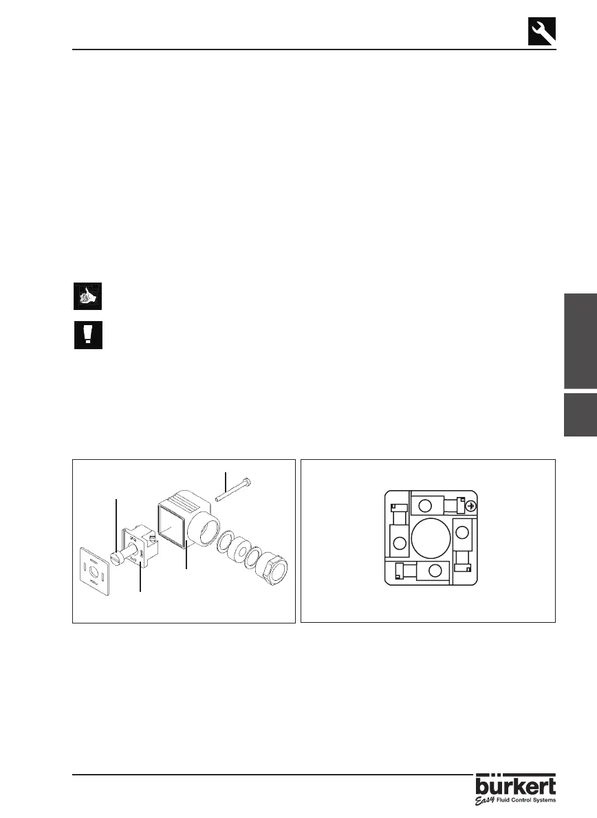
3.4.1 WIRING VIA A CABLE PLUG
Fig. 3.3 Plug assembly
1.To open the connector remove screws
and including the plastic ring (Fig. 3.3).
2.Remove the internal part from the external casing with a screwdriver blade.
3.Connect the transmitter according to the pin assignment in Fig. 3.4
4.When re-assembling, the internal part can be rotated in 90°steps to a desired
position before inserting back into the casing .
Fig. 3.4 Pin assignment
1: L+ (18-32VDC)
2: 4-20 mA Output
3: L-
쵰: Earth
1
2
3
훰훫훫
훫훫훱
훫훫훱
L+
(18-32VDC)
4-20 mA
Output
L-
훫훫훱
Earth
3.4