17
8175
ENGLISH
INSTALLATION
4-20 mA
18-32 VDC
+
-
250 mA
SW1
-+I
REL 2
REL 1
R2
R1
R2
R1
3 A
3 A
m
24VDC
230VAC
PT1000
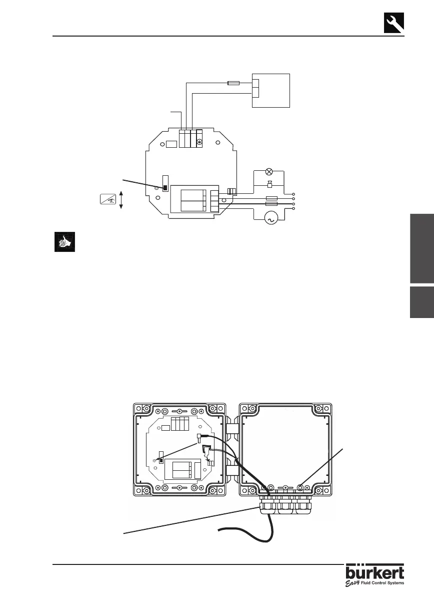
8175 PANEL VERSION, RELAY CONNECTION
The relay version is connected as follows :
3.4.3
Fig. 3.13 Pin assignment for
relays
SW 1
● The device can be easily connected to a PLC independently of the
respective version.
● The ‘Enter‘ key can be locked by placing the SW 1 swich into the up
position to avoid accidental or unauthorided access.
3.4.4 8175 WALL MOUNTED VERSION 18-32VDC
CONNECTION OF THE 8170 SENSOR
● Remove the cover via the screws on the front display and remove the PG 9 as
indicated passing the cable through the hole.
● Secure the PG 9 supplied on the cable to the box using the plasic nut and
secure the cable.
● Connect the coax and PT1000 temperature cables as shown in the diagram below.
PG 9 to remove
Plastic nuts
Fig. 3.14 Wall cable connections
ENTER
Lock
Unlock