9
8175
ENGLISH
INSTALLATION
3.1 GENERAL INSTALLATION GUIDELINES
Prior to the installation of the 8175 ultrasonic level transmitter, a clear mounting
location for the product must be determined.
● The level transmitter or sensor types 8175 / 8170 are designed for
liquid level measurement. It is the user responsability to test the
functionality of the device for any other material such as powders,
granuals etc.
● The 8175 ultrasonic level transmitter or sensor must be installed
perpendicular to the process medium.
● Ensure a minimum distance of 30 cm between the level of the fluid
and the sensor is respected.
The tank or vessel should be surveyed to locate potential obstructions which
may interfere with the beam cone. Such obstructions may include: fill pipes and
streams; mixers and agitators; tank side walls and rungs.
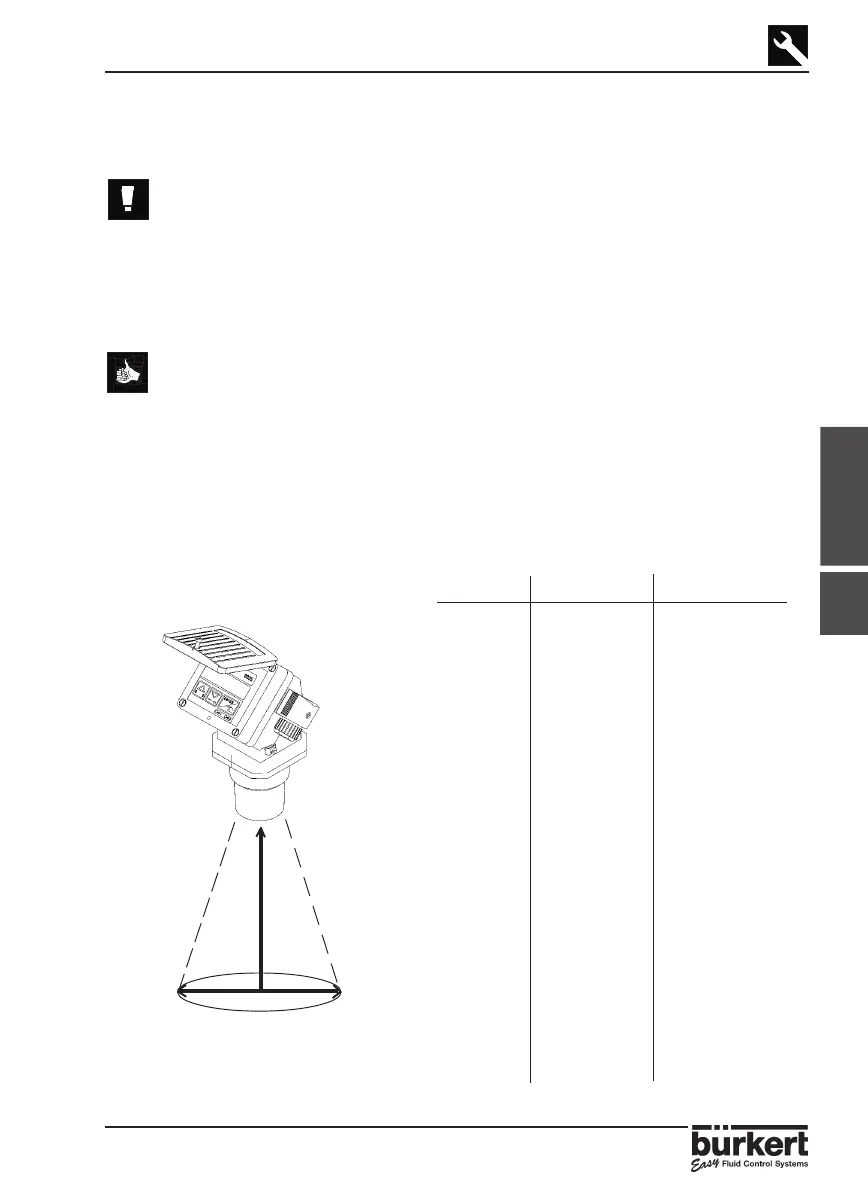
3.1.1 Beam cone diameter
The ultrasonic level transmitter type 8175 generates 8 pulses per second which is
emitted from the base of the transducer. As the pulses leave the transmitter, they
expand to an 8° beam angle until they are reflected back via the process medium.
To determine the maximum diameter of the beam cone for the application select the
maximum length (L) from the table below.
Fig. 3.1 Length and Diameter
Relationship
Diameter (D cm)
8°
Length (L cm)
Min 30 cm
3.1
LD L DL D
30 4 360 50 690 96
40 6 370 52 700 98
50 7 380 53 710 99
60 8 390 55 720 101
70 10 400 56 730 102
80 11 410 57 740 103
90 13 420 59 750 105
100 14 430 60 760 106
110 15 440 62 770 108
120 17 450 63 780 109
130 18 460 64 790 110
140 20 470 66 800 112
150 21 480 67 810 113
160 22 490 69 820 115
170 24 500 70 830 116
180 25 510 71 840 117
190 27 520 73 850 119
200 28 530 74 860 120
210 29 540 76 870 122
220 31 550 77 880 123
230 32 560 78 890 124
240 34 570 80 900 126
250 35 580 81 910 127
260 36 590 83 920 129
270 38 600 84 930 130
280 39 610 85 940 131
290 41 620 87 950 133
300 42 630 88 960 134
310 43 640 90 970 136
320 45 650 91 980 137
330 46 660 92 990 138
340 48 670 94 1000 140
350 49 680 95