16
8175
ENGLISH
INSTALLATION
4-20 mA
+
-
18-32 VDC
+
-
250 mA
I
SW1
-+I
PT1000
4-20 mA
+
-
18-32 VDC
+
-
250 mA
I
SW1
-+I
PT1000
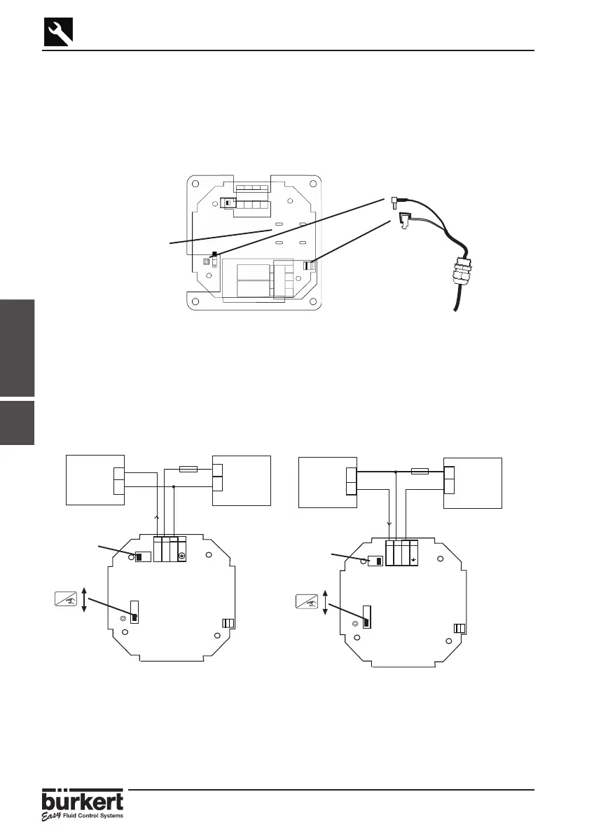
3.4.3
3.4.3 8175 PANEL VERSION 18-32VDC
CONNECTION OF THE 8170 SENSOR
● Pass the cable through the wall / panel and use the PG 9 to secure the cable.
● Connect the coax and PT1000 temperature cables shown in the diagram below.
● Secure all the cables onto the protection plate as indicated via the 2 plastic ties
provided.
PT1000
Coax
Secure the cables
onto the protection
plate using the plastic
ties
SW 2,
Position A
SW 2,
Position B
8175 PANEL VERSION 18-32VDC, WIRING
Open the cabinet/cupboard and wire according to the pin assignment diagrams below.
The electronics within the 8175 allows a sourcing or sinking PLC to be connected.
Position A (Fig 3.11) provides a sourcing configuration and Position B (Fig 3.12) a
sinking configuration.
Fig. 3.11 Pin assignment, Position A Fig. 3.12 Pin assignment, Position B
ENTER
Lock
Unlock
ENTER
Lock
Unlock
Fig. 3.10 Panel cable connections
PLC/control
valve or
positioner
PLC/control
valve or
positioner