15
8175
ENGLISH
INSTALLATION
-+I
2
REL 1
REL
230
N
L1
115/230VAC
N
L1
T315mA
230V
-
+
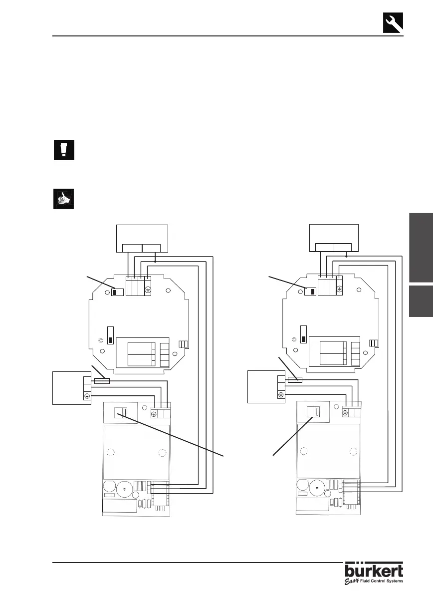
3.4.2
8175 COMPACT VERSION, 115/230 VAC
WIRING
Remove the cover via the screws on the front display and pull the cable through the
PG 13.5 and wire according to one of the pin assignment diagrams below.
The electronics within the 8175 allows a sourcing or sinking PLC to be connected.
Position A (Fig 3.5) provides a sourcing configuration and Position B (Fig 3.6) a
sinking configuration.
● Do not open and wire the transmitter with the power supply
connected.
● Ensure that the power supply switch is selected for the appropriate
voltage 115VAC or 230 VAC.
The connection for relays 1 and 2 are identical to that of the 18-32VDC on the
previous page.
POWER
SUPPLY
SWITCHES
Fig. 3.8 Pin assignment, Position A Fig. 3.9 Pin assignment, Position B
-+I
2
REL 1
REL
230
N
L1
115/230VAC
N
L1
T315mA
230V
+
-
SW 2,
Position A
SW 2,
Position B
Fuse - 5A
Fuse - 5A
PLC/control valve/
positioner 4-20mA
PLC/control valve/
positioner 4-20mA