14
8175
ENGLISH
INSTALLATION
3.4.2
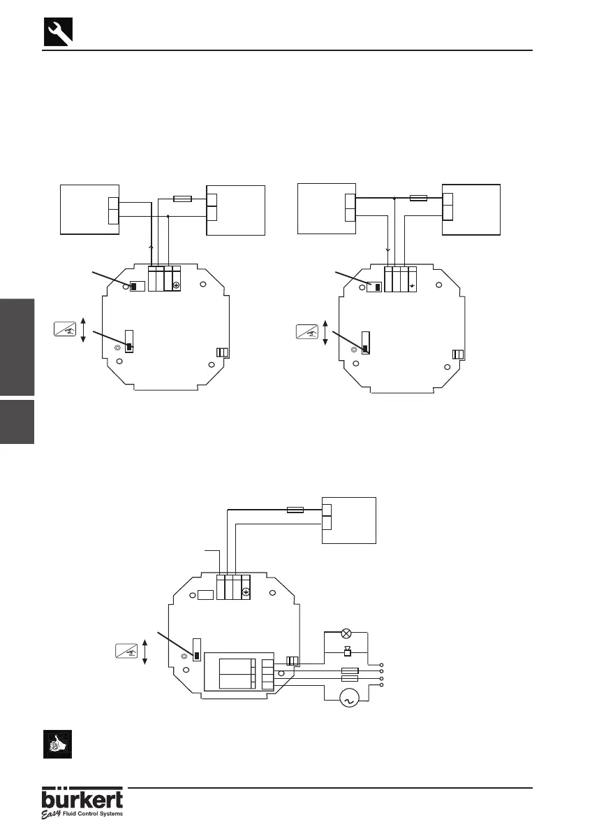
3.4.2 8175 COMPACT VERSION, 18-32 VDC, WITH PG 13.5
WIRING
Remove the cover via the screws on the front display and pull the cable through the
PG 13.5 and wire according to one of the pin assignment diagrams below.
The electronics within the 8175 allows a sourcing or sinking PLC to be connected.
Position A (Fig 3.5) provides a sourcing configuration and Position B (Fig 3.6) a
sinking configuration.
Fig. 3.5 Pin assignment, Position A Fig. 3.6 Pin assignment, Position B
8175 COMPACT VERSION, RELAY CONNECTION
The electrical wiring of this model is possible via the use of 2 cable glands. Remove
the cover via the screws on the front display and pull the cables through the PG 13.5
and wire according to pin assignment diagram below (Fig. 3.7).
● The device can be easily connected to a PLC independently of the
respective version.
● The ‘Enter‘ key can be locked by placing the SW 1 swich into the up
position to avoid accidental or unauthorided access.
4-20 mA
+
-
18-32 VDC
+
-
250 mA
I
SW1
-+I
PT1000
4-20 mA
+
-
18-32 VDC
+
-
250 mA
I
SW1
-+I
PT1000
PLC/control
valve or
positioner
ENTER
Lock
Unlock
ENTER
Lock
Unlock
SW 2,
Position A
SW 2,
Position B
Fig. 3.7 Pin assignment for relays
4-20 mA
18-32 VDC
+
-
250 mA
SW1
-+I
REL 2
REL 1
R2
R1
R2
R1
3 A
3 A
m
24VDC
230VAC
PT1000
SW 1
ENTER
Lock
Unlock
PLC/control
valve or
positioner