18
8175
ENGLISH
INSTALLATION
4-20 mA
18-32 VDC
+
-
250 mA
SW1
-+I
REL 2
REL 1
R2
R1
R2
R1
3 A
3 A
m
24VDC
230VAC
PT1000
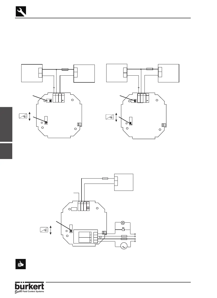
8175 WALL MOUNTED VERSION, 18-32 VDC; WIRING
Remove the cover via the screws on the front display and pull the cable through the
PG 9 and wire according to one of the pin assignment diagrams below.
The electronics within the 8175 allows a sourcing or sinking PLC to be connected.
Position A (Fig 3.15) provides a sourcing configuration and Position B (Fig 3.16) a
sinking configuration.
Fig. 3.15 Pin assignment, Position A Fig. 3.16 Pin assignment, Position B
8175 WALL MOUNTED VERSION, RELAY CONNECTION
The electrical wiring of this model is possible via the use of 2 of the cable glands.
Remove the cover via the screws on the front display and pull the cables through the
PG 9 and wire according to pin assignment diagram below (Fig. 3.17).
● The device can be easily connected to a PLC independently of the
respective version.
● The ‘Enter‘ key can be locked by placing the SW 1 swich into the up
position to avoid accidental or unauthoridsed access.
4-20 mA
+
-
18-32 VDC
+
-
250 mA
I
SW1
-+I
PT1000
4-20 mA
+
-
18-32 VDC
+
-
250 mA
I
SW1
-+I
PT1000
ENTER
Lock
Unlock
ENTER
Lock
Unlock
SW 2,
Position A
SW 2,
Position B
Fig. 3.17 Pin assignment for relays
3.4.4
PLC/contact
valve or
positioner
PLC/contact
valve or
positioner
SW 1
ENTER
Lock
Unlock