19
MC-III™ Panel Mount Flow Analyzer Section 2
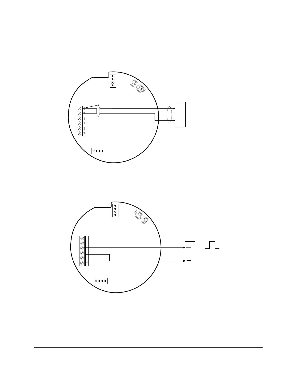
Input Wiring
Turbine Flow Meter (TFM) Input
The TFM input provides the turbine ow meter input signal generated by a magnetic pickup, enabling the
MC-III Panel Mount to calculate and display instantaneous ow rates and accumulated totals.
6
-
3
0
V
D
C
TB1
PULSE
INPUT
RESET
INPUT
TFM
A&S
GND
TB
3
EXT POWER
TURBINE
MAGNETIC PICKUP
J1
J2
RESET
SWITCH
BATTERY
A
B
Figure 2.3—Flow meter input wiring
Pulse Input
The pulse input provides an optically isolated input in systems where a preamplier is inserted between the
sensor and the MC-III Panel Mount.
T
B
3
TB1
PULSE
INPUT
RESET
INPUT
TFM
A&S
GND
EXT POWER
6
-
3
0
V
D
C
J1
J2
RESET
SWITCH
BATTERY
PULSE INPUT
3 TO 30 VDC
Figure 2.4—Pulse input wiring
For a list of recommended pickup adapters,
see the parts list on 92.
Vturbine max = 5.0 Vdc or peak
Voc = 1.0 Vdc
Isc = 5.0 mA max
Ca = 30 µF max
La = 2 H max
 Loading...


