89
MC-III™ Panel Mount Flow Analyzer Section 6
Circuit Assembly Replacement
Important: Static electricity can damage a circuit board. Handle new boards only by their edges,
and use proper anti-static techniques (such as wearing anti-static wrist strap or touching
metal to establish an earth ground) prior to handling a board.
Important: If possible, record the accumulated total and all conguration settings before replacing
the circuit board. This information can be recorded by hand or captured by saving a con-
guration le that can be reloaded into the unit after the circuit board is replaced. (See
Saving and Uploading Conguration Files, page 69.)
To replace the circuit assembly, perform the following steps:
1. Record the locations of all cable connections to the circuit assembly.
2. Using a small standard blade screwdriver, remove all wiring from terminal blocks TB1, TB2, and TB3,
ensuring that all wiring that is connected to powered circuits is insulated with tape.
3. Unplug the battery cable from connector J1 on the circuit assembly (Figure 6.1, page 88).
4. Using a athead screwdriver, remove the two standoff screws connecting the metal plate/battery assembly
to the circuit board.
5. Unscrew the two threaded standoffs to remove them from the circuit board.
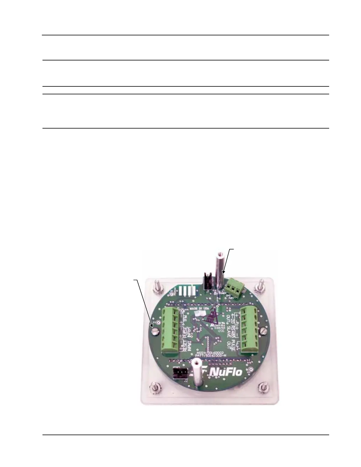
6. Using a small athead screwdriver, remove the two screws from the circuit assembly (Figure 6.2). Handle
the board with care, noting that it is still attached to the keypad on the under side by a ribbon cable.
Mounting screw
(2, typ.)
Standoffs
(2, typ.)
Figure 6.2—Removal of circuit assembly