90
Section 6 MC-III™ Panel Mount Flow Analyzer
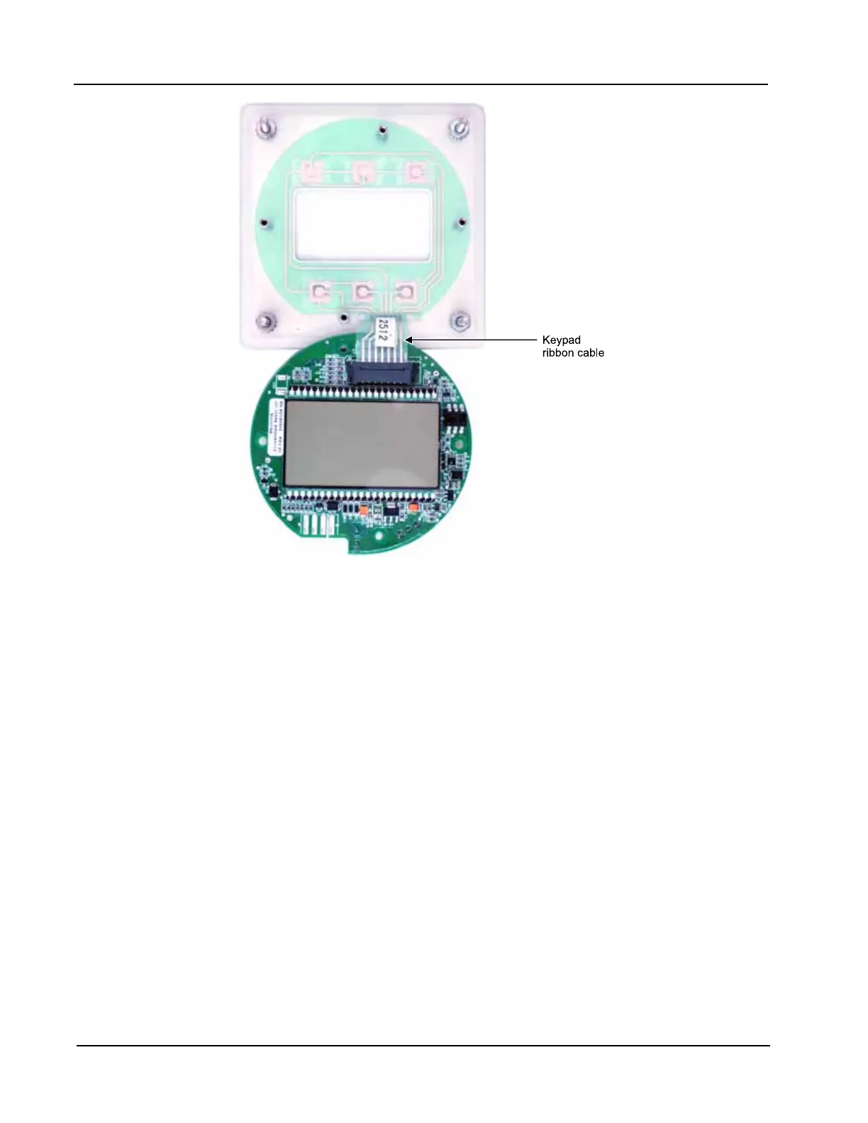
Figure 6.3—Keypad ribbon cable connection
6. Vertically ip the circuit board over so that the LCD is facing you and gently disconnect the keypad rib-
bon cable from connector J3 (Figure 6.3) as follows:
a. Grasp the black clip between a thumb and forenger (see arrows in Figure 6.4, page 91).
b. Squeeze both sides of the clip and gently pull to release the clip from the plastic connector that holds
it in place. DO NOT PULL on the ribbon cable. When the black plastic clip is properly disengaged,
the cable will release freely.
7. Remove the new circuit assembly from any packaging and connect the ribbon cable of the keypad to con-
nector J3 on the LCD side of the circuit assembly as follows:
a. Insert the end of the ribbon cable into the plastic clip.
b. While holding the ribbon cable in place, press the black plastic clip into the connector until it snaps.
8. Reconnect the battery cable to connector J1 on the circuit assembly.
9. Center the circuit assembly over the two standoffs on either side of the keypad and secure with the
screws removed in step 5.
10. Reconnect all wiring to terminal blocks TB1, TB2 and TB3.
11. Recalibrate the MC-III Panel Mount.
12. Restore power to the peripheral circuitry.
 Loading...


