67
MC-III™ Panel Mount Flow Analyzer Section 4
Pulse Output
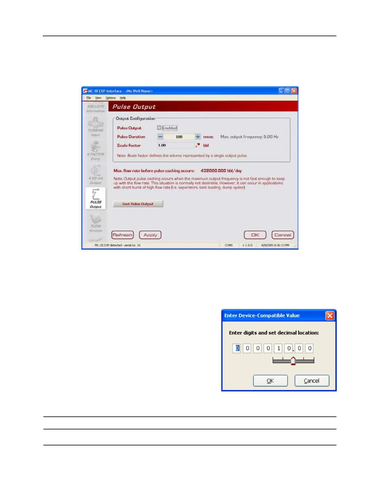
The Pulse Output screen (Figure 4.31) allows users to congure the MC-III Panel Mount to provide a pulse
output representing increments in volume. A test mode function is also included, allowing a user to calibrate
and/or verify the output received by an end device.
Figure 4.31—Pulse Output screen
Conguring Pulse Output
By default, the pulse output option is disabled to reduce current consumption. To conserve power, do not
enable this feature unless it will be used.
To enable the pulse output option, perform the following steps:
1. Check the “Enable” checkbox.
2. Enter the pulse duration value using the “plus” and “minus”
buttons on the screen, or the page-up and page-down keys
on a computer keyboard. The pulse length (pulse width)
determines the length of each output pulse in milliseconds
(ms).
3. Click on the pencil icon next to the scale eld to open a
data-entry window (Figure 4.32), and enter the scale factor.
Adjust the decimal position, if necessary, using the slide bar.
The scale factor sets the volume increment that will cause a
pulse output to occur. The unit for this factor is determined
by the unit set for the volume display.
Figure 4.32—Data-entry screen for pulse
output scale factor
Note: The scale factor can be any number; it is not limited to powers of 10 (1, 10, 100, etc.).