23
MC-III™ Panel Mount Flow Analyzer Section 2
TB1
PULSE
INPUT
RESET
INPUT
TFM
A&S
GND
T
B
3
EXT POWER
TB2
RS485
SLAVE
4-20
OUT
PULSE
OUT
6
-
3
0
V
D
C
J1
J2
RESET
SWITCH
BATTERY
Leave this
end of shield
disconnected.
POWER SUPPLY
5 to 30 VDC
FREQUENCY
READOUT DEVICE
*
Resistor may be included in frequency
readout device. Size the resistor to limit
the current to 50 mA.
4-20 mA and flowmeter frequency
(amp & square) cannot be used
simultaneously.
*
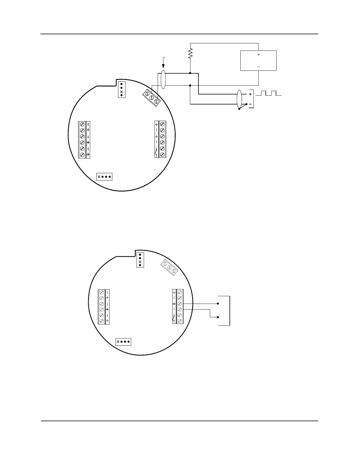
Figure 2.9—Flow meter frequency (amp & square) output wiring
RS-485 Output
The RS-485 output is required for communication with the interface software. Wiring diagrams are provided
for a permanent connection (Figure 2.10), as well as for temporary laptop connections using an RS-485 to RS-
232 converter (Figure 2.11 and Figure 2.12, page 24).
A
B
TB1
PULSE
INPUT
RESET
INPUT
TFM
A&S
GND
TB
3
EXT POWER
TB2
RS485
SLAVE
4-20
OUT
PULSE
OUT
6
-
3
0
V
D
C
RS-485
Communications
J1
J2
RESET
SWITCH
BATTERY
Figure 2.10—RS-485 output (permanent connection)