22
Section 2 MC-III™ Panel Mount Flow Analyzer
TB1
PULSE
INPUT
RESET
INPUT
TFM
A&S
GND
TB
3
EXT POWER
TB2
RS485
SLAVE
4-20
OUT
PULSE
OUT
6
-
3
0
V
D
C
J1
J2
RESET
SWITCH
BATTERY
POWER SUPPLY
8 to 30 VDC
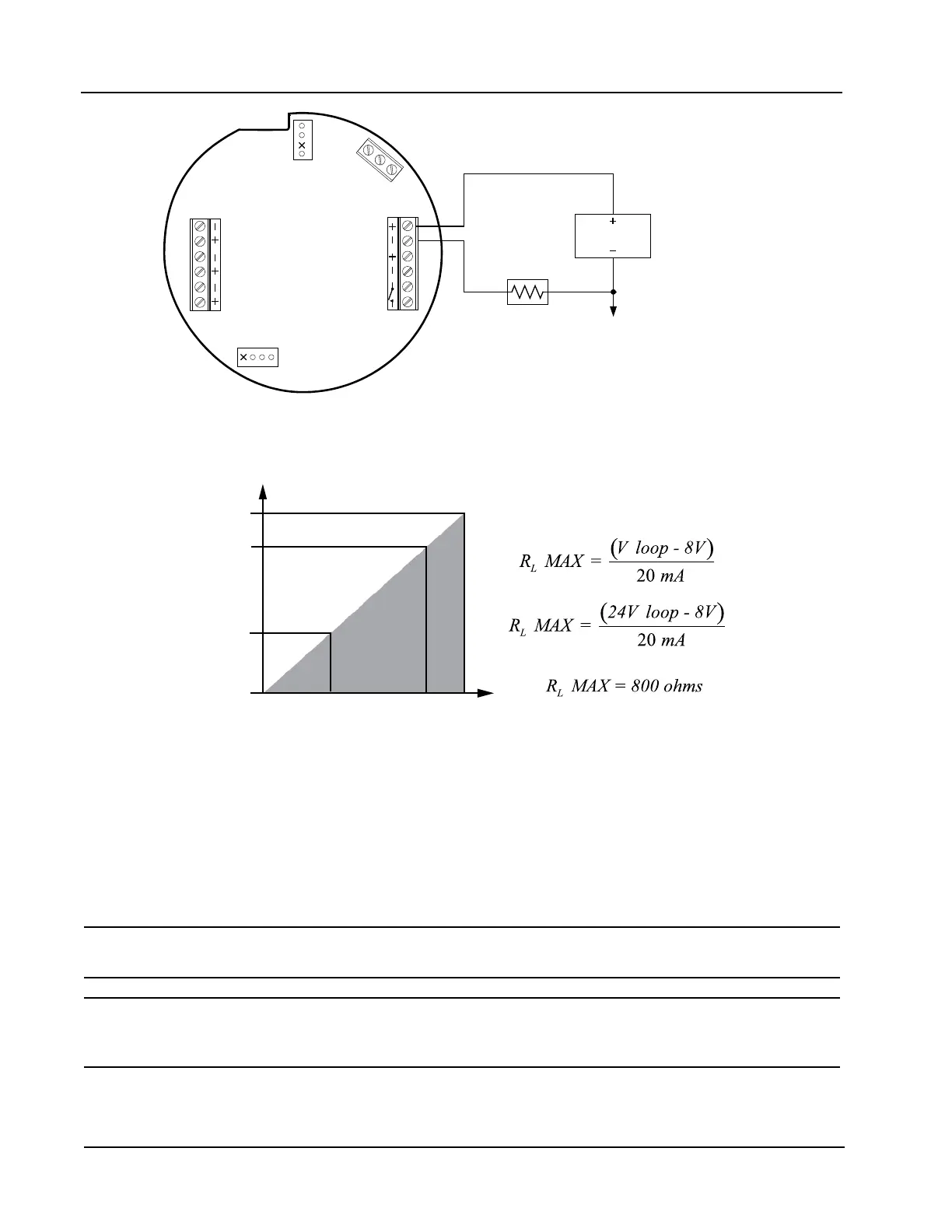
LOAD
Resistor may be
included in readout
device.
4-20 mA and
flowmeter frequency
(amp & square)
cannot be used
simultaneously.
*
*
1100
800
200
0
LOAD RESISTANCE (OHMS)
8 12 24 30
LOOP SUPPLY VOLTAGE (VDC)
OPERATING
REGION
Figure 2.8—4-20 mA rate output wiring
Flow Meter Frequency Output
The ow meter frequency (amp & square) output provides an open drain transistor output at the turbine meter
frequency, which may be used to provide ow rate and/or total information to peripheral equipment. The
output requires a two-conductor cable from the MC-III Panel Mount to the remote frequency readout device
requiring 50 mA or less and a 5 to 30 VDC power supply (Figure 2.9, page 23).
Caution: The ow meter frequency output and 4-20 mA rate output are not isolated from each
other and cannot be used simultaneously.
Caution: When using the ow meter frequency output and powering the device from an
external power supply, make sure both power supplies share a common negative (-)
terminal or are totally isolated from each other.
The ow meter frequency output terminals on the MC-III Panel Mount circuit assembly are labeled A & S to
represent “amp & square” output.