Chapter 6
6-35
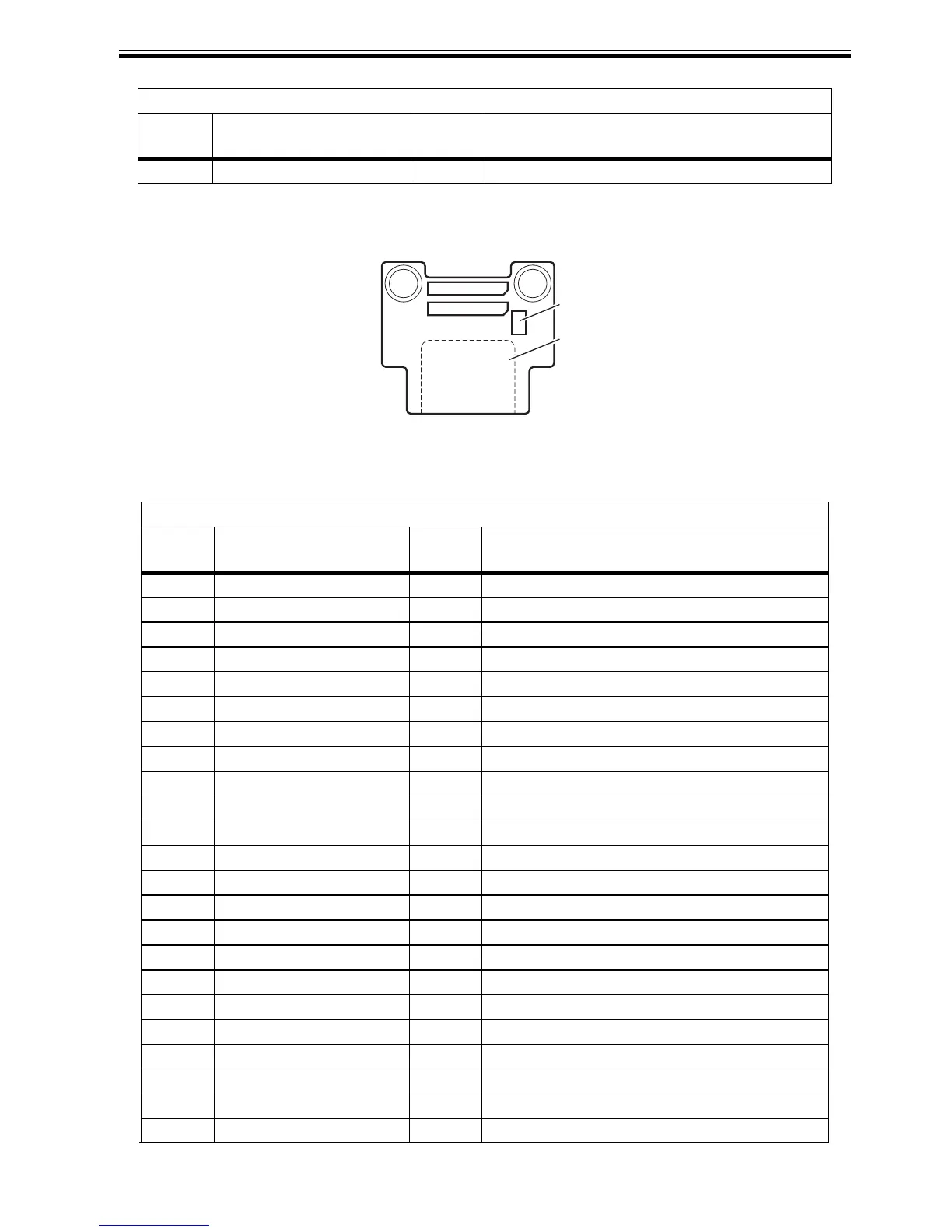
6.2.3 Head relay PCB
0012-6417
F-6-3
T-6-24
50 IO-ASIC_SCL IN/OUT Head ROM control signal (clock)
J101
Pin
Number
Signal name IN/OUT Function
1 VMGND - GND
2 PWLED1 IN Multi sensor LED1 drive signal
3 PWLED2 IN Multi sensor LED2 drive signal
4 PWLED3 IN Multi sensor LED3 drive signal
5 PWLED4 IN Multi sensor LED4 drive signal
6 VMGND - GND
7 H3V IN Power supply (+3V)
8 VH1_FB IN VH feed back voltage -
9 VH1 IN Power supply
10 VH1 IN Power supply
11 VH1 IN Power supply
12 VH1 IN Power supply
13 VH1 IN Power supply
14 VH1 IN Power supply
15 VMGND - GND
16 VMGND - GND
17 VMGND - GND
18 VMGND - GND
19 VMGND - GND
20 VMGND - GND
21 VH2 IN Power supply
22 VH2 IN Power supply
23 VH2 IN Power supply
J702
Pin
Number
Signal name IN/OUT Function
J201
J601
J101
J102
 Loading...