EasyManuals Logo
Home>Canon>Printer>imagePROGRAF IPF700

Canon imagePROGRAF IPF700 Service Manual

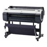
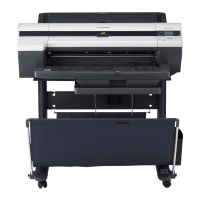
Canon imagePROGRAF IPF700
202 pages
To Next Page IconTo Next Page
To Previous Page IconTo Previous Page
Page #47 background imageLoading...
Page #47 background image
Chapter 2
2-1
2.1 Basic Operation Outline
2.1.1 Printer Diagram
0012-6242
A printer diagram is shown below.
F-2-1
J3401
J3201J3202J3002J2501 J2502
J3602J3601J2702J3001J1301J2801J2601
Main controler PCB
Linear encoder
Carriage cover sensor
Upper cover lock
solenoid(R)
Upper cover lock
solenoid(L)
Upper cover switch
Upper cover switch
Valve motor
Ink tank cover switch
Carriage motor
Head management sensor
Feed roller motor
Printhead
Multi sensor
J101J102J103
J601J702J703
J201J202
J101
J201
J601
J102J103
Head relay PCB
Carriage
relay PCB
Ink tank ROM PCB (L)
Ink tank ROM PCB (R)
Humidity sensor
Carriage HP sensor
Lift motor
Pressure release switch
Pump motor
Pump encoder sensor
Pump cam sensor
Media sensor
J2701
Feed roller encoder
Feed roller HP sensor
Suction fan
Mist fan (R)
Mist fan (L)
Maintenance cartridge
J1801
J3301
Power supply
Operation panel
J2 J1
Maintenance cartridge ROM PCB
Valve open/closed detection Sensor

Table of Contents

Other manuals for Canon imagePROGRAF IPF700

Questions and Answers:

Question and Answer IconNeed help?

Do you have a question about the Canon imagePROGRAF IPF700 and is the answer not in the manual?

Canon imagePROGRAF IPF700 Specifications

General IconGeneral
BrandCanon
ModelimagePROGRAF IPF700
CategoryPrinter
LanguageEnglish

Related product manuals