Chapter 2
2-32
2.5 Detection Functions with Sensors
2.5.1 Sensers for covers
0012-6321
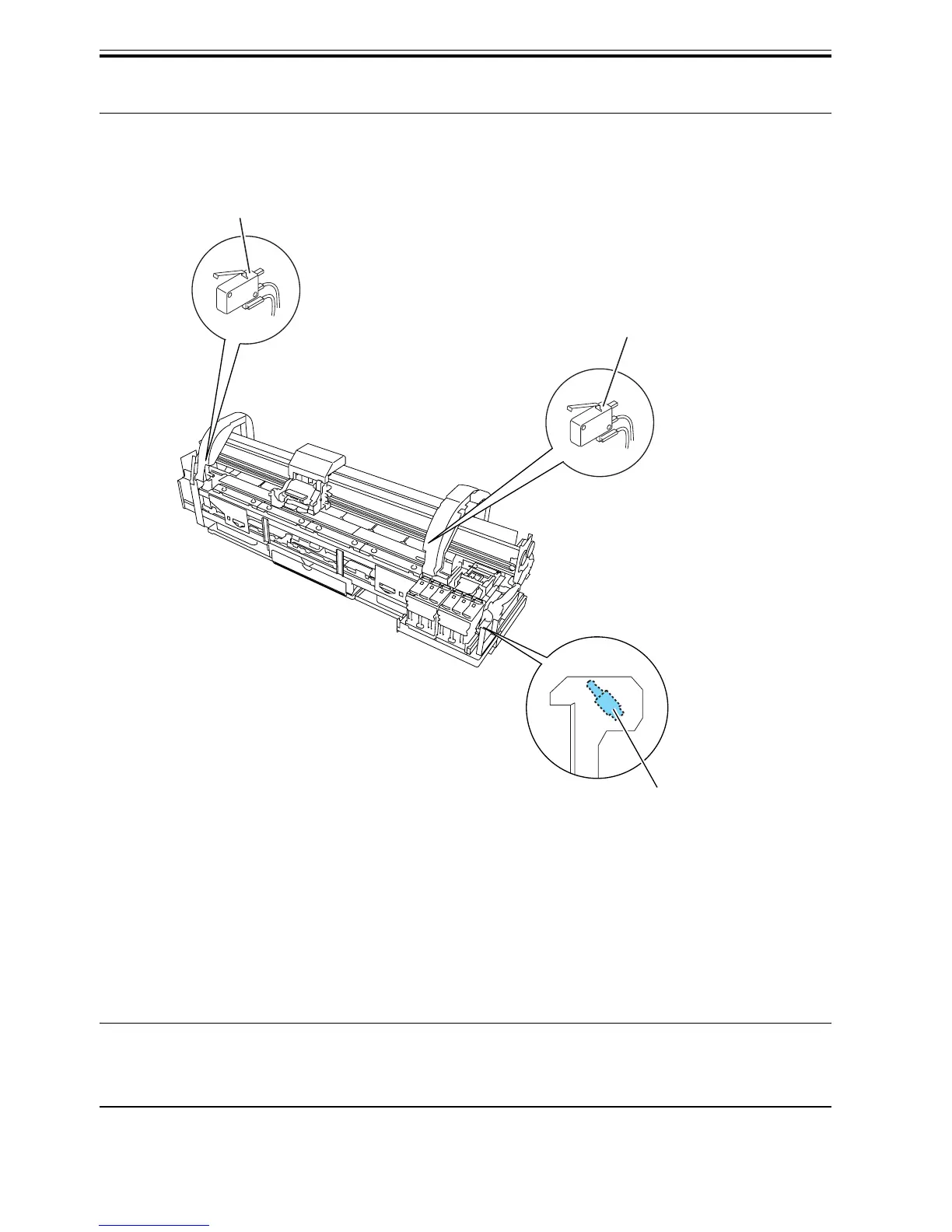
F-2-27
Upper cover lock switch
The micro switch-based Upper cover lock switch detects the open/closed states of the upper cover.
When the upper cover closes, the switch is pressed to detect the closed state of the cover.
The printer has one sensor installed on the left and right sides each to prevent one-sided tightening of the upper
cover.
Ink tank cover switch
The micro switch-based Ink tank cover switch detects the open/closed states of the ink tank cover.
When the ink tank cover closes, the switch is pressed to detect the closed state of the cover.
Memo:
+26.5V is supplied from the power supply unit to drive the carriage motor and the feed motor while the top cover
is closed.
Ink tank cover switch
Upper Cover lock switch(left)
Upper cover lock switch(right)
 Loading...