Chapter 2
2-21
a) Caps
The caps cap the nozzle assembly in the printhead during cleaning. The part of the caps that comes into contact
with the face plate of the nozzle assembly is made of rubber. Two caps are in position to meet the printhead
mounted on the printhead (six trains of nozzles).
These caps cap the nozzle assembly to suck inks from the printhead by means of the suction pump.
The caps are elevated by the cap cam that is driven by the purge motor when the carriage moves to the home
position, capping the nozzle assembly to protect it.
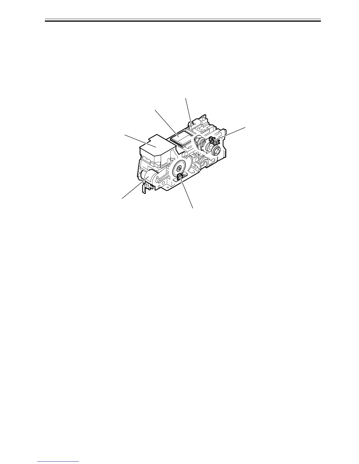
F-2-13
Carriage lockpin
Glycerin tank
Purge motor
Pump encoder
Pump cam sensor
Cap
 Loading...