7
GB-21
8.4 Note On Adding Refrigerant
Note: 1) Please use tools for R410A/R32 system respectively;
2) The standard pipe length is 7.5m (24.6’). When the pipe length is over 7.5m, the additional
refrigerant should be added according to the piping length.
8.5 Safety And Leakage Check
CAUTION
• Refrigerant charging must be performed after wiring, vacuuming, and the leak testing.
•
DO NOT exceed the maximum allowable quantity of refrigerant or overcharge the system.
Doing so can damage the unit or impact it’s functioning.
•
Charging with unsuitable substances may cause explosions or accidents. Ensure that the
appropriate refrigerant is used.
Refrigerant containers must be opened slowly. Always use protective gear when charging the system.
•
•
DO NOT mix refrigerants types.
N=2(one-twin models), N=3(one-three models), N=4(one-four models), N=5(one-five models).Depending on the length
of connective piping or the pressure of the evacuated system, you made need to add refrigerant. Refer to table
below for refrigerant amounts to be added:
ADDITIONAL REFRIGERANT PER PIPE LENGTH
Connective Pipe
Length
Air Purging
Method
Additional Refrigerant
(
R410A/R32)
Pre-charge pipe length(ft/m)
(Standard pipe lengthxN)
Vacuum Pump
N/A
More than
(Standard pipe lengthxN)ft/m
Vacuum Pump
Liquid Side: Ø 6.35 (Ø 1/4”)
(Total pipe length - standard pipe lengthxN) x15g/m /
(Total pipe length - standard pipe lengthxN) x12g/m
Liquid Side: Ø 9.52 (Ø 3/8”)
(Total pipe length - standard pipe lengthxN) x30g/m /
(Total pipe length - standard pipe lengthxN) x24g/m
Electrical safety check
Perform the electrical safety check after
completing installation. Cover the following areas:
1. Insulated resistance
The insulated resistance must be more than 2MΩ.
2. Grounding work
After finishing grounding work, measure the grounding
resistance by visual detection and using the grounding
resistance tester.
Make sure the grounding resistance is less than 4Ω.
3. Electrical leakage check (performing during test while
unit is on)
During a test operation after completed installation,
use the electroprobe and multimeter to perform an
electrical leakage check. Turn off the unit immediately
if leakage happens. Try and evaluate different solutions
until the unit operates properly.
Gas leak check
1. Soap water method:
Apply a soap-water solution or a liquid neutral detergent
on the indoor unit connection or outdoor unit connections
with a soft brush to check for leakage of the connecting
points of the piping. If bubbles emerge, the pipes are
experiencing leakage.
2. Leak detector
Use the leak detector to check for leakage.
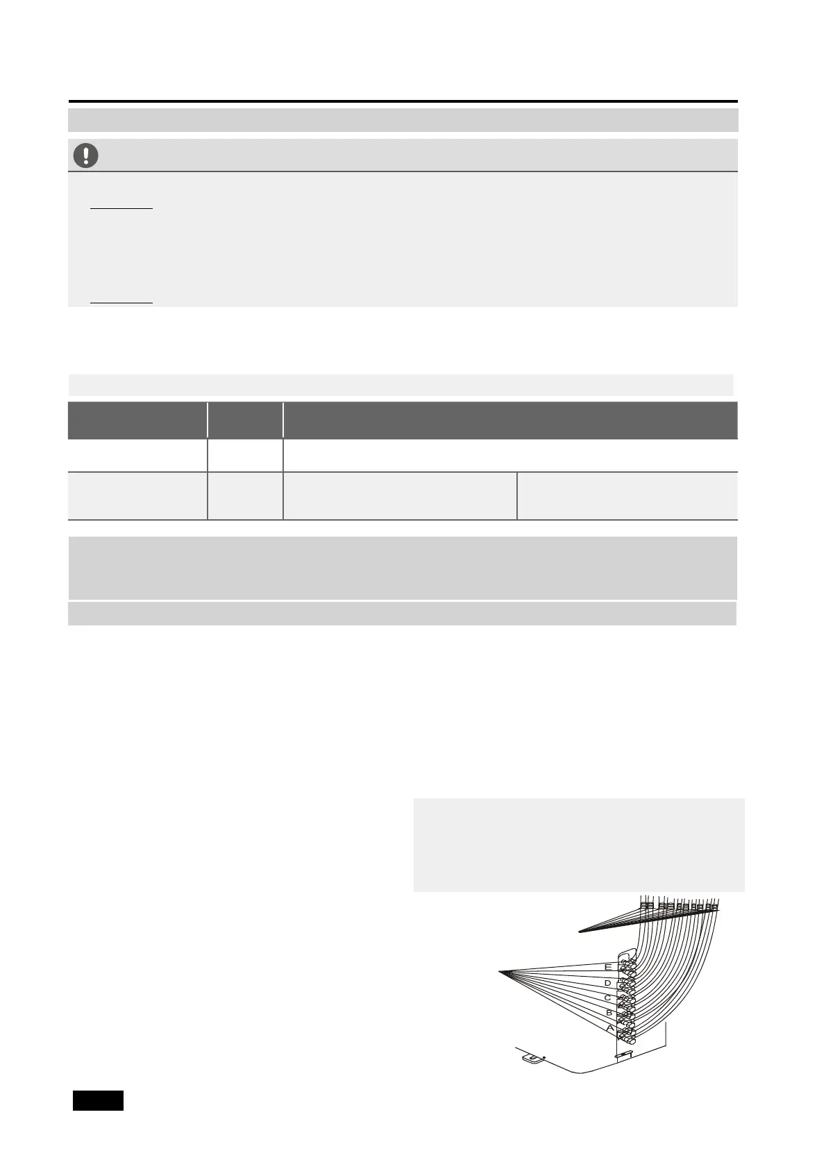
NOTE: The illustration is for example purposes
only. The actual order of A, B, C, D, and E on the
machine may be slightly different from the unit
you purchased but the general shape will remain
the same.
Indoor unit
check point
Outdoor unit
check point
A, B,C,D are points for the one-four type.
A, B,C,D, and E are points for the one-five type.
Fig. 8.4
8. AIR EVACUATION
 Loading...