SERViCE MANUAL
R&R AND OVERHAUL
Aii Modeis
111.
With the engine and speed gearbox assembly
separated from the range section, remove hydraulic
lift housing as outlined in paragraph 137 or 138. Re-
move the differential assembly as in paragraph 115.
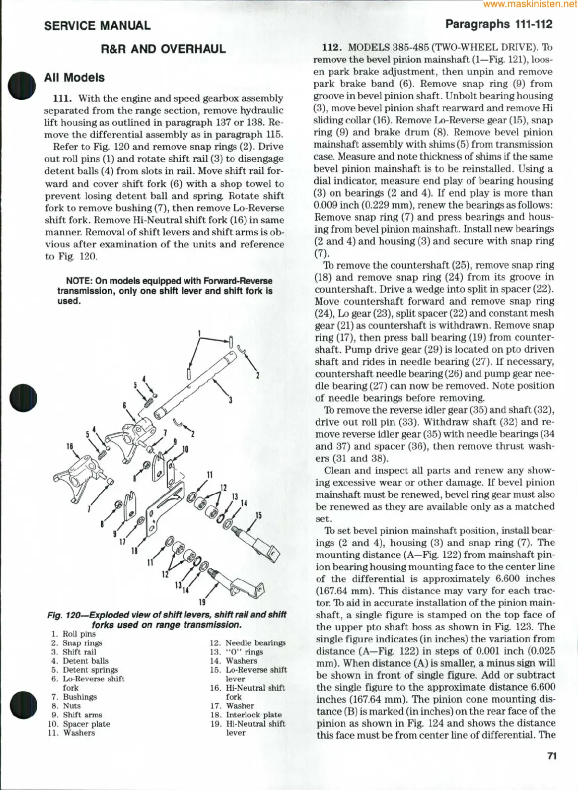
Refer to Fig. 120 and remove snap rings (2). Drive
out roll pins (1) and rotate shift rail (3) to disengage
detent balls (4) from slots in rail. Move shift rail for-
ward and cover shift fork (6) with a shop towel to
prevent losing detent ball and spring. Rotate shift
fork to remove bushing
(7),
then remove Lo-Reverse
shift fork. Remove Hi-Neutral shift fork (16) in same
manner. Removal of shift levers and shift arms is ob-
vious after examination of the units and reference
to Fig. 120.
NOTE:
On modeis equipped with Fbrward-Reverse
transmission, only one siiift iever and shift foric is
used.
Fig.
120—Exploded
view of shift
levers,
shift rail and
shift
forks used on range transmission.
1.
Roll pins
2.
Snap rings 12. Needle bearings
3.
Shift rail 13. *'O" rings
4.
Detent balls 14. Washers
5.
Detent springs 15. Lo-Reverse shift
6. Lo-Reverse shift lever
fork 16. m-Neutral shift
7. Bushings fork
8. Nuts 17. Washer
9. Shift arms 18. Interlock plate
10.
Spacer plate 19. Hi-Neutral shift
11.
Washers lever
Paragraphs 111-112
112.
MODELS 385-485 (TWO-WHEEL DRIVE). Ib
remove the bevel pinion mainshaft
(1—Fig.
121), loos-
en park brake adjustment, then unpin and remove
park brake band (6). Remove snap ring (9) from
groove in bevel pinion shaft. Unbolt bearing housing
(3),
move bevel pinion shaft rearward and remove Hi
sliding collar
(16).
Remove Lo-Reverse gear
(15),
snap
ring (9) and brake drum (8). Remove bevel pinion
mainshaft assembly with shims (5) from transmission
case.
Measure and note thickness of shims if the same
bevel pinion mainshaft is to be reinstalled. Using a
dial indicator, measure end play of bearing housing
(3) on bearings (2 and 4). If end play is more than
0.009 inch (0.229 mm), renew the bearings as follows:
Remove snap ring (7) and press bearings and hous-
ing from bevel pinion mainshaft. InstaU new bearings
(2 and 4) and housing (3) and secure with snap ring
(7).
Ib remove the countershaft (25), remove snap ring
(18) and remove snap ring (24) from its groove in
countershaft. Drive a wedge into split in spacer (22).
Move countershaft forward and remove snap ring
(24),
Lo gear
(23),
split spacer (22) and constant mesh
gear (21) as countershaft is withdrawn. Remove snap
ring (17), then press ball bearing (19) from counter-
shaft. Pump drive gear (29) is located on pto driven
shaft and rides in needle bearing (27). If necessary,
countershaft needle bearing (26) and pump gear nee-
dle bearing (27) can now be removed. Note position
of needle bearings before removing.
Tb
remove the reverse idler gear (35) and shaft (32),
drive out roll pin (33). Withdraw shaft (32) and re-
move reverse idler gear (35) with needle bearings (34
and 37) and spacer (36), then remove thrust wash-
ers (31 and 38).
Clean and inspect all parts and renew any show-
ing excessive wear or other damage. If bevel pinion
mainshaft must be renewed, bevel ring gear must also
be renewed as they are available only as a matched
set.
Ib set bevel pinion mainshaft position, install bear-
ings (2 and 4), housing (3) and snap ring (7). The
mounting distance
(A—Fig.
122) from mainshaft pin-
ion bearing housing mounting face to the center line
of the differential is approximately 6.600 inches
(167.64 mm). This distance may vary for each trac-
tor Ib aid in accurate installation of the pinion main-
shaft, a single figure is stamped on the top face of
the upper pto shaft boss as shown in Fig. 123. The
single figure indicates (in inches) the variation from
distance (A-Fig. 122) in steps of 0.001 inch (0.025
mm).
When distance (A) is smaller, a minus sign will
be shown in front of single figure. Add or subtract
the single figure to the approximate distance 6.600
inches (167.64 mm). The pinion cone mounting dis-
tance (B) is marked (in inches) on the rear face of the
pinion as shown in Fig. 124 and shows the distance
this face must be from center Une of differential. The
71



 To Next Page