SERVICE MANUAL
Paragraph 113 (Cont.)
ings (7 and 9) and housing (8) on bevel pinion while
rotating the housing. Apply pressure until a slight
preload can be felt. InstaU spacer
(11).
Snap ring (12)
is available in thicknesses of 0.066, 0.069, 0.072, 0.075,
0.078,
0.081,
0.084, 0.087, 0.090 and 0.093 inch (1.67,
1.75, 1.83, 1.90, 1.98, 2.06, 2.13, 2.21, 2.28 and 2.36
mm).
Select the thinnest snap ring, 0.066 inch (1.67
mm) and instaU in its groove. Make certain that bear-
ing (9) and spacer
(11)
are tight against snap ring (12),
then using a dial indicator, measure end play of hous-
ing (8) on bearings (7 and 9). Add the end play to the
thickness of instaUed snap ring. The result is the cor-
rect thickness of snap ring to be installed. Remove
the thin snap ring and install the new one. This as-
sembly will now have a maximum end play of 0.003
inch (0.076 mm) or a maximum preload of 0.002 inch
(0.050 mm).
Ib remove the countershaft (25), remove snap ring
(18) and remove snap ring (24) from its groove in
countershaft. Drive a wedge into split in spacer (22).
Move countershaft forward and remove snap ring
(24),
Lo gear
(23),
spUt spacer (22) and constant mesh
gear (21) as countershaft is withdrawn. Remove snap
ring
(17),
then press baU bearing from countershaft.
Pump drive gear (29) is located on pto driven shaft
and rides in needle bearing (27). If necessary, coun-
tershaft needle bearing and pump gear needle bear-
ing (27) can now be removed. Note position of nee-
dle bearings before removing.
Ib remove the reverse idler gear (35) and shaft (32),
drive out roU pin (33). Withdraw shaft (32) and re-
move reverse idler gear (35) with needle bearings (34
and 37) and spacer (36), then remove thrust wash-
ers (31 and 38).
Clean and inspect aU parts and renew any show-
ing excessive wear or other damage. If bevel pinion
mainshaft must be renewed, bevel ring gear
(1)
must
also be renewed as they are available only as a
matched set.
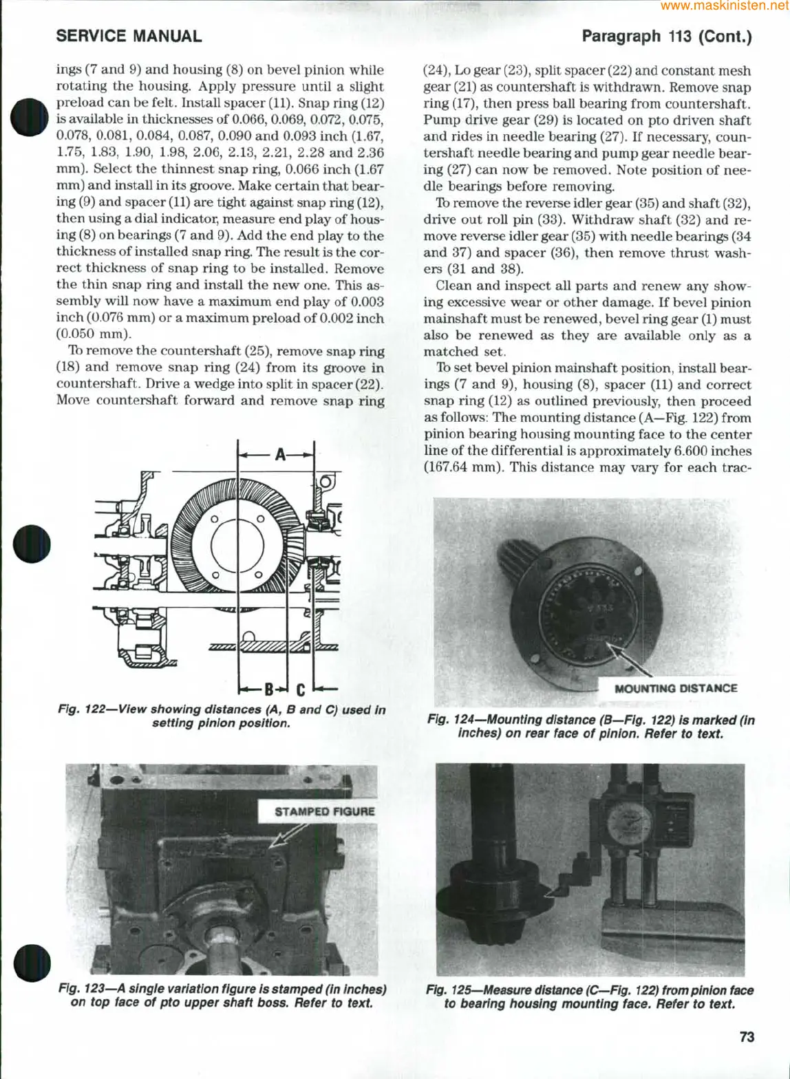
Ib set bevel pinion mainshaft position, instaU bear-
ings (7 and 9), housing (8), spacer (11) and correct
snap ring (12) as outlined previously, then proceed
as follows: The mounting distance
(A—Fig.
122) from
pinion bearing housing mounting face to the center
line of the differential is approximately 6.600 inches
(167.64 mm). This distance may vary for each trac-
Fig. 122—View showing distances (A, B and C) used in
setting pinion position.
DfSTAHOE
Fig. 124—Mounting distance (B—Fig. 122) is marked (in
inches) on rear face of pinion. Refer to
text.
Fig.
123—A
single variation figure Is stamped (in inches)
on top face of pto upper shaft boss. Refer to
text.
Fig.
125—Measure distance
(C—Fig.
122) from pinion
face
to bearing housing mounting face. Refer to
text.
73
 Loading...


