SECTION 55 - ELECTRICAL SYSTEM 179
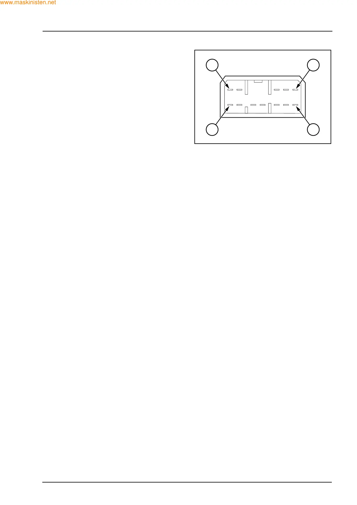
FRONT INSTRUMENT CLUSTER CONNECTOR -
AMPERE 070 12-WAY POWERSHIFT
Pin functions and test procedure
Listed below are the pin numbers, warning lights,
and gauges.
1. Starter switch key 12 V
2. Ground:
check continuity
3. Tachometer:
signal from W output of the alternator
4. Dipped beam:
green warning light illuminates at 12 V with multi
function light switch on
5. Main beams - Blue warning light illuminates at
12 V with multi function switch on
6. 12 V and instrument backlighting
7. Not used
8. 4WS - Green warning light four wheel input. With
Ignition ON and 4WS selected 0.5 V should be
indicated.
With 2WS or crab steer selected, 0 V should be
indicated.
9. Crab steer - Green warning light
10. 2WS - Green warning light 2WS input. With Igni-
tion ON and 2WS selected 1.5 V should be indi-
cated.
With 4WS or crab steer selected, 12 V should be
indicated.
11. Direction indicators:
green warning light illuminates at 12 V with light
switch on
12. Brake oil level:
red warning light when the input is connected to
ground with ignition on 12 V
F28412
5 1
12 6
 Loading...


