180 SECTION 55 - ELECTRICAL SYSTEM
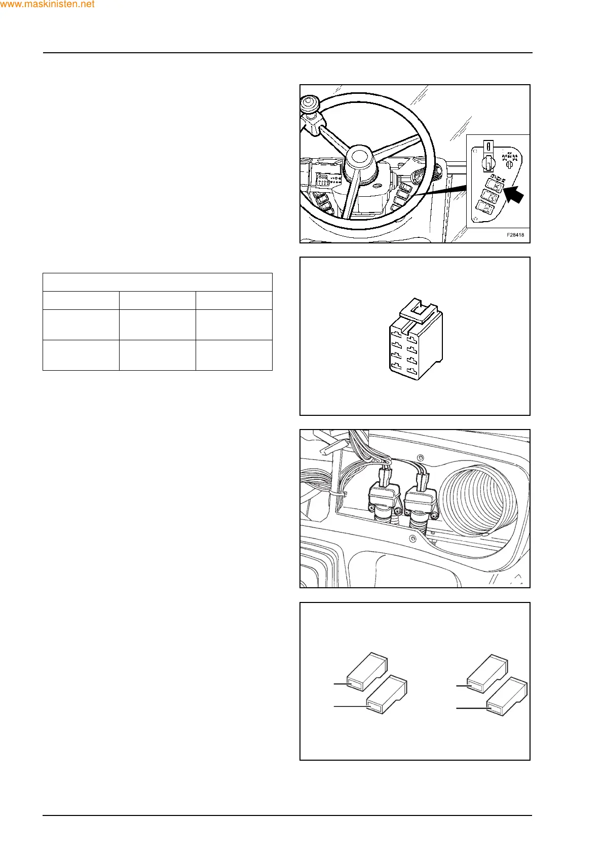
8.9 4WD SWITCH
Test procedure
Voltage:
Ignition ON: Pin 3 = 12 V
Pin 6 = 9 V
8.10 BRAKE PEDAL SWITCHES
Test Procedure
Continuity:
Brakes not applied: no continuity.
Brakes applied: continuity, between the two centre
pins of each switch.
Both brake pedals must be applied to allow 12 V to
relay.
Voltage:
Left switch:
White / red wire 12 V continuous with ignition
ON
Red wire 12 V pedal depressed
0 V pedal released
Right switch:
Red wire 12 V pedal depressed
0 V pedal released
Red - Black wire 12 V pedal depressed
0 V pedal released
Continuity
Switch OFF Position 1 Position 2
From pin 7
to pin 5
From pin 5
to pin 3
From pin 1
to pin 3
From pin 6
to pin 8
From pin 4
to pin 6
From pin 2
to pin 4
F28417
F28419
F28420
1: R:1
2: R-N:1
1: R:1
2: B/R:1
 Loading...


