SECTION 55 - ELECTRICAL SYSTEM 185
8.18 STEERING CONTROL UNIT
The steering control unit controls the different steer-
ing functions that can be selected from the switch
S47.
When changing steering mode, the light for the cur-
rent mode is extinguished and the light for the new
mode starts to flash. When movement of the steer-
ing wheel is detected, the light for the new mode re-
mains steady.
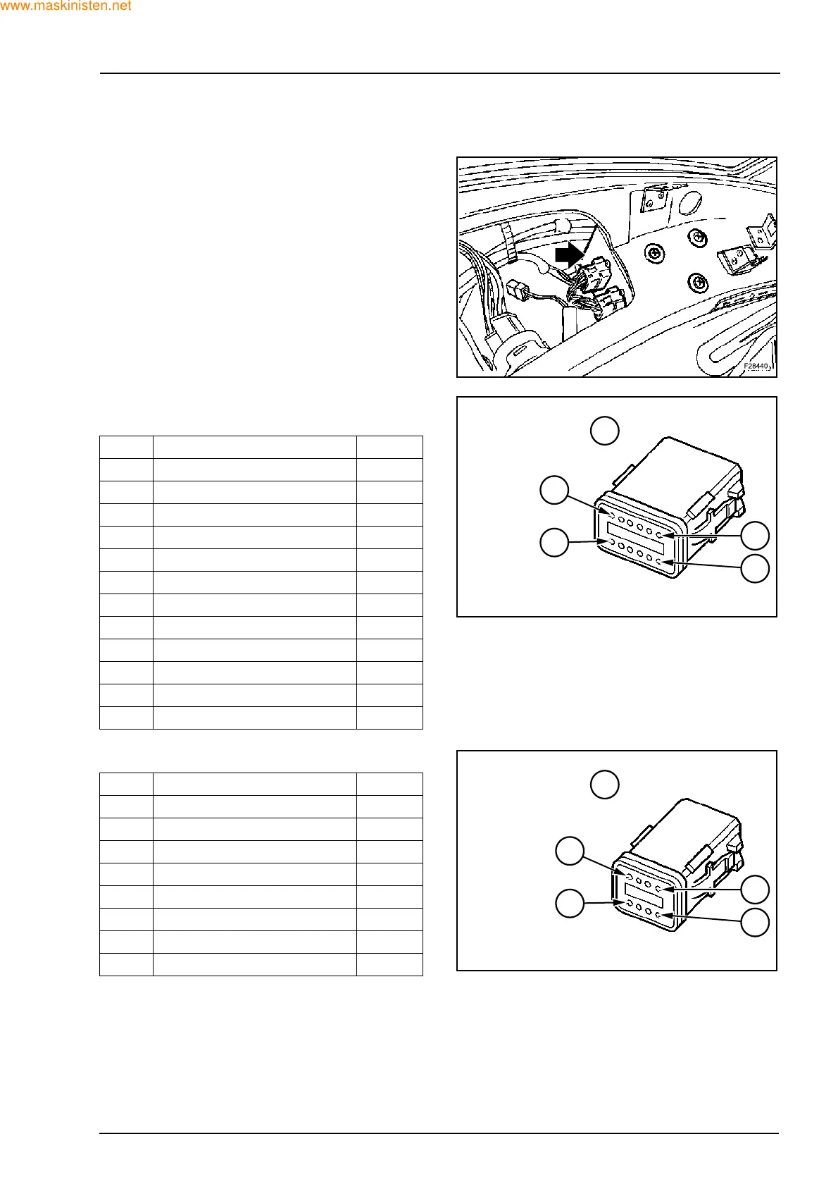
Connector pin out description
12 pin connector -X95:
8 pin connector -X96:
Pin Function Signal
1 Crab steering warning light -
2 Buzzer configuration -
3 Front alignment sensor input +12
4 Crab steering control +12
5 Buzzer output -
6 Rod iron steering control +12
7 Control unit supply +12
8 Ground -
9 Speed sensor input -
10 Rear alignment sensor input +12
11 2WS warning light -
12 4WS warning light -
Pin Function Signal
1 EV2A output +12
2 EV2B output +12
3 EV3A output +12
4 Ground -
5 Front sensor supply output +12
6 Rear sensor supply output +12
7 Available optional output +12
8 EV3B output +12
F28441
12
1
7
6
1: CM:Z/B:1.5
2: CM:C:1
3: CM:H-L:1.5
4: CM:A-R:1
5: CM:V-B:1
6: CM:V/N:1
7: CM:R-G:1
8: CM:N:1
9: CM:A-B:1
10: CM:L/N:1
11: CM:M:1
12: CM:V/B:1
X95
F28442
8
1
5
4
1: CM:L/R:1
2: CM:S/N:1
3: CM:H/N:1
4: CM:L-N:1
5: CM:A/V:1
6: CM:R/N:1
7:
8: CM:M/B:1
X96
 Loading...


