SECTION 35 - HYDRAULIC SYSTEM 33
Removal
Z Lower the loader to the ground, with the bucket
firmly placed on the ground.
Z Stop the engine and relieve any residual pressure
in the backhoe and loader attachment systems by
moving the relevant control levers through all oper-
ating positions.
Z Disconnect the battery.
Z Clean the area around the control valve.
Z Identify and disconnect linkage, cables and each
hose connection to the control valve and plug the
hose ends. A drip tray will be required to catch oil
draining from inside the hoses.
Z Unscrew and remove clamping screws to chassis.
Z Remove the valve assembly from the machine.
Z Installation is the reverse of the removal procedure.
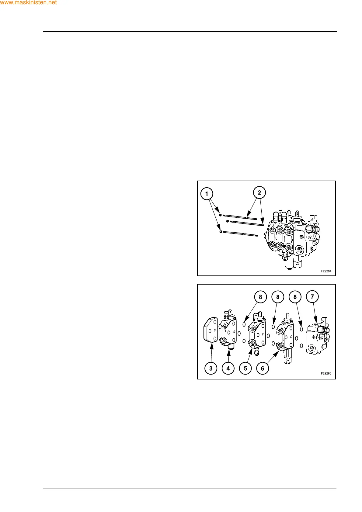
Disassembly
Unscrew and remove the three nuts (1). Tightening
torque 27 ± 2 Nm. Slide out the three tie bars (2).
Disassemble the end cover (4), the section control
valve (4), (5) and (6), and the inlet section (7).
Check and possibly replace the O-rings (8) located
between the section control valves.