34 SECTION 35 - HYDRAULIC SYSTEM
REAR CONTROL VALVE (WITH MECHANICAL CONTROL)
The rear control valve is located in the rear part of the
loader backhoe. It consists of six or seven valve sec-
tions together with an inlet and outlet end cover.
Valve sections are:
Z Right-hand stabilizer
Z Stabilizer left
Z Lifting
Z Crowd
Z Swing
Z Bucket
Z Telescopic (optional)
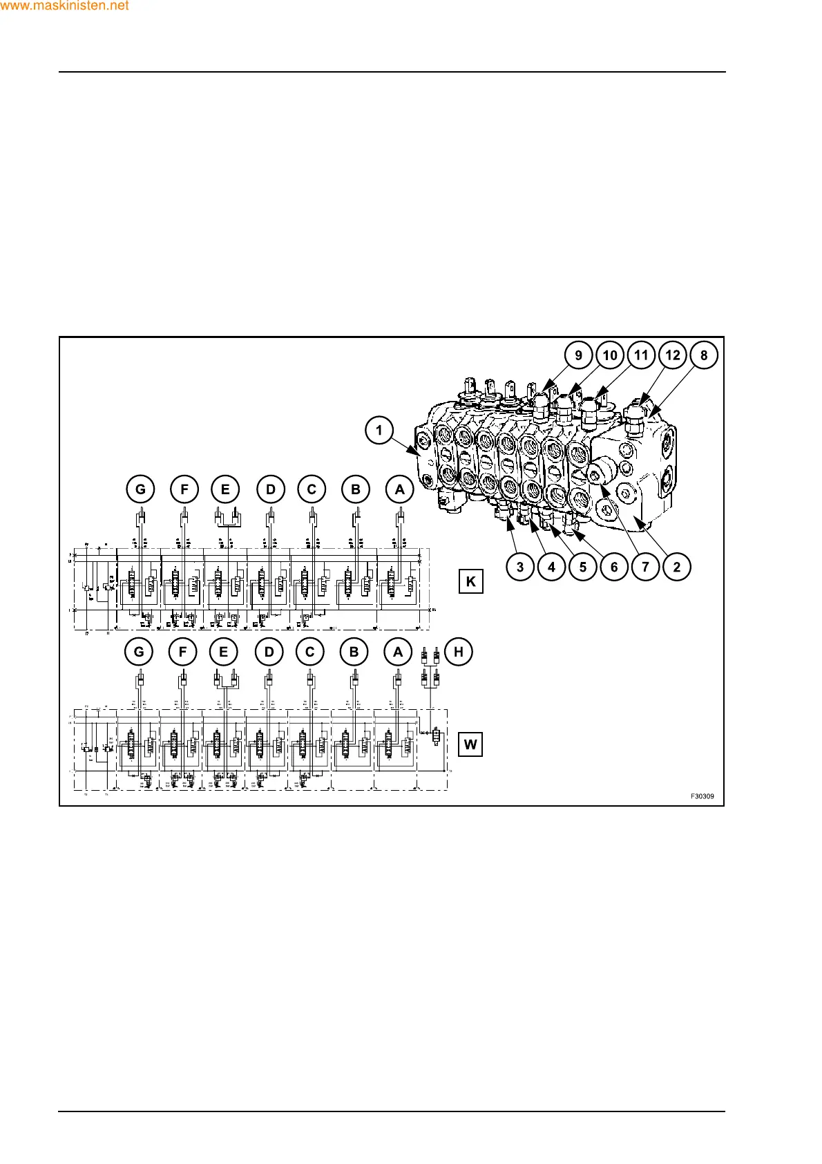
K. Hydraulic diagram for center pivot models
(4WS)
W. Hydraulic diagram for sideshift models
A. Right stabilizer section
B. Left stabilizer section
C. Dipper section
D. Bucket section
E. Swing section
F. Lifting section
G. Telescopic dipper section
H. Backhoe attachment travel lock valve (sideshift)
1. End cover
2. Inlet section
3. Dipper circuit relief valve (piston end) - 240 bar
4. Backhoe bucket circuit relief valve (piston end) -
220 bar
5. Swing circuit relief valve (piston end) - 205 bar
6. Boom system relief valve (piston end) - 315 bar
7. Pump flow balancer - 15 bar
8. Load sensing return to tank
9. Swing circuit relief valve (rod end) - 205 bar
10. Boom relief valve (rod end) - 240 bar
11. Telescopic relief valve (rod end) - 205 bar
12. Load sensing relief valve - 210 bar