SECTION 35 - HYDRAULIC SYSTEM 35
Removal
Z Position the loader backhoe on a hard level sur-
face.
Z Lower the loader attachment to the ground.
Z Lower the stabilizers.
Z Position the dipper in the vertical position, with the
bucket firmly placed on the ground.
Z Stop the engine and relieve any residual pressure
in the backhoe and loader attachment systems by
moving the relevant control levers through all oper-
ating positions.
Z Disconnect the battery.
Z Clean the area around the control valve.
Z Tag and identify the position of all hoses.
Z Disconnect and plug all the hoses.
Z Disconnect the levers of the manual control.
Z Unscrew and remove clamping screws to chassis.
Z Remove the valve assembly from the loader back-
hoe.
Z Installation is removal procedure in reverse.
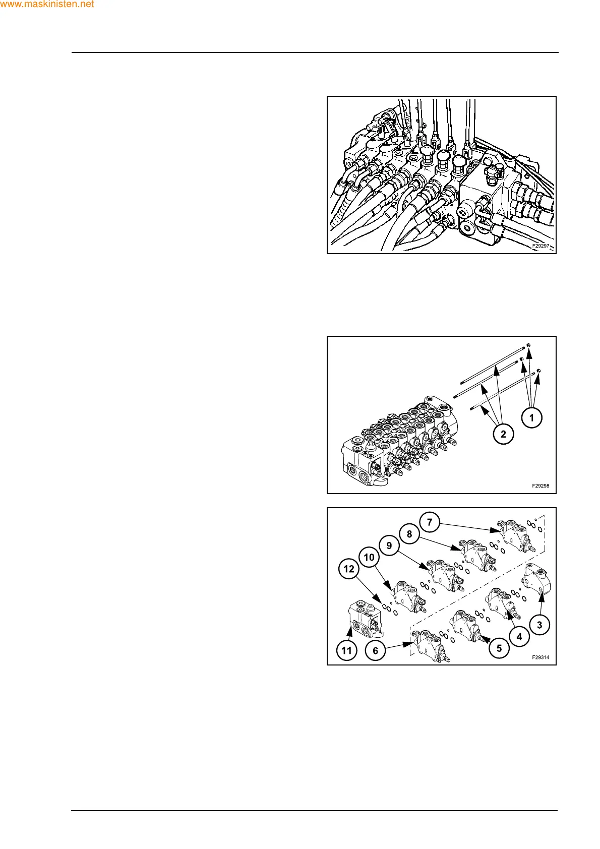
Disassembly
Unscrew and remove the three nuts (1), tightening
torque 27 ± 2 Nm.
Slide out the three tie bars (2).
Disassemble the end cover (3), the sections control
valves (4), (5), (6), (7), (8), (9) and (10), the inlet sec-
tion (11).
Check and possibly replace the O-rings (12) located
between the section control valves.