36 SECTION 35 - HYDRAULIC SYSTEM
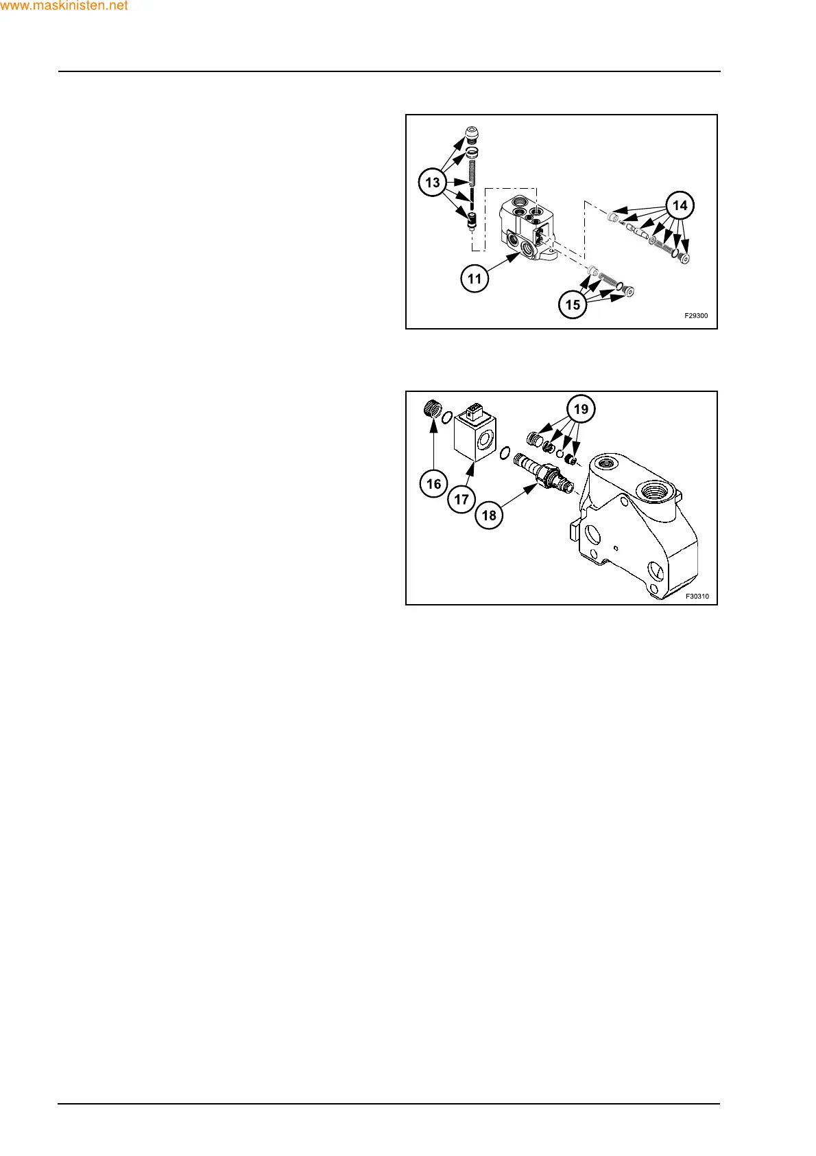
Disassembly the inlet section.
Remove the pump flow balancer valve (13), the load
sensing relief valve (14) and the check valve (15)
from the inlet section (11).
Disassembly the outlet section.
(Sideshift version)
Unscrew the knob (16).
Remove the solenoid (17) and the 2 way valve (18).
Disassembly the shuttle valve (19).