SECTION 35 - HYDRAULIC SYSTEM 43
Removal
Lower the loader to the ground, with the bucket firmly
placed on the ground.
Stop the engine and relieve any residual pressure in
the backhoe and loader attachment systems by mov-
ing the relevant control levers through all operating
positions.
Disconnect the battery.
Clean the area around the control valve.
Identify and disconnect linkage, cables and each
hose connection to the control valve and plug the
hose ends. A drip tray will be required to catch oil
draining from inside the hoses.
Unscrew and remove clamping screws to chassis.
Remove the valve assembly from the machine.
Installation is the reverse of the removal procedure.
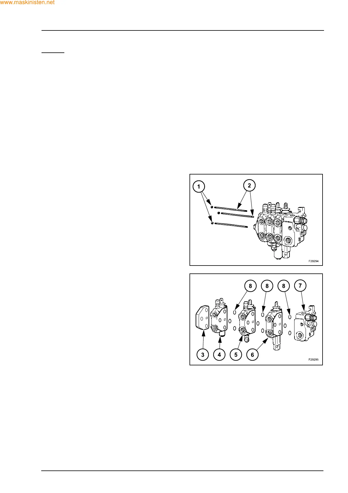
Disassembly
Unscrew and remove the three nuts (1). Tightening
torque 27 ± 2 Nm. Slide out the three tie bars (2).
Disassemble the end cover (4), the section control
valve (4), (5) and (6), and the inlet section (7).
Check and possibly replace the O-rings (8) located
between the section control valves.