48 SECTION 35 - HYDRAULIC SYSTEM
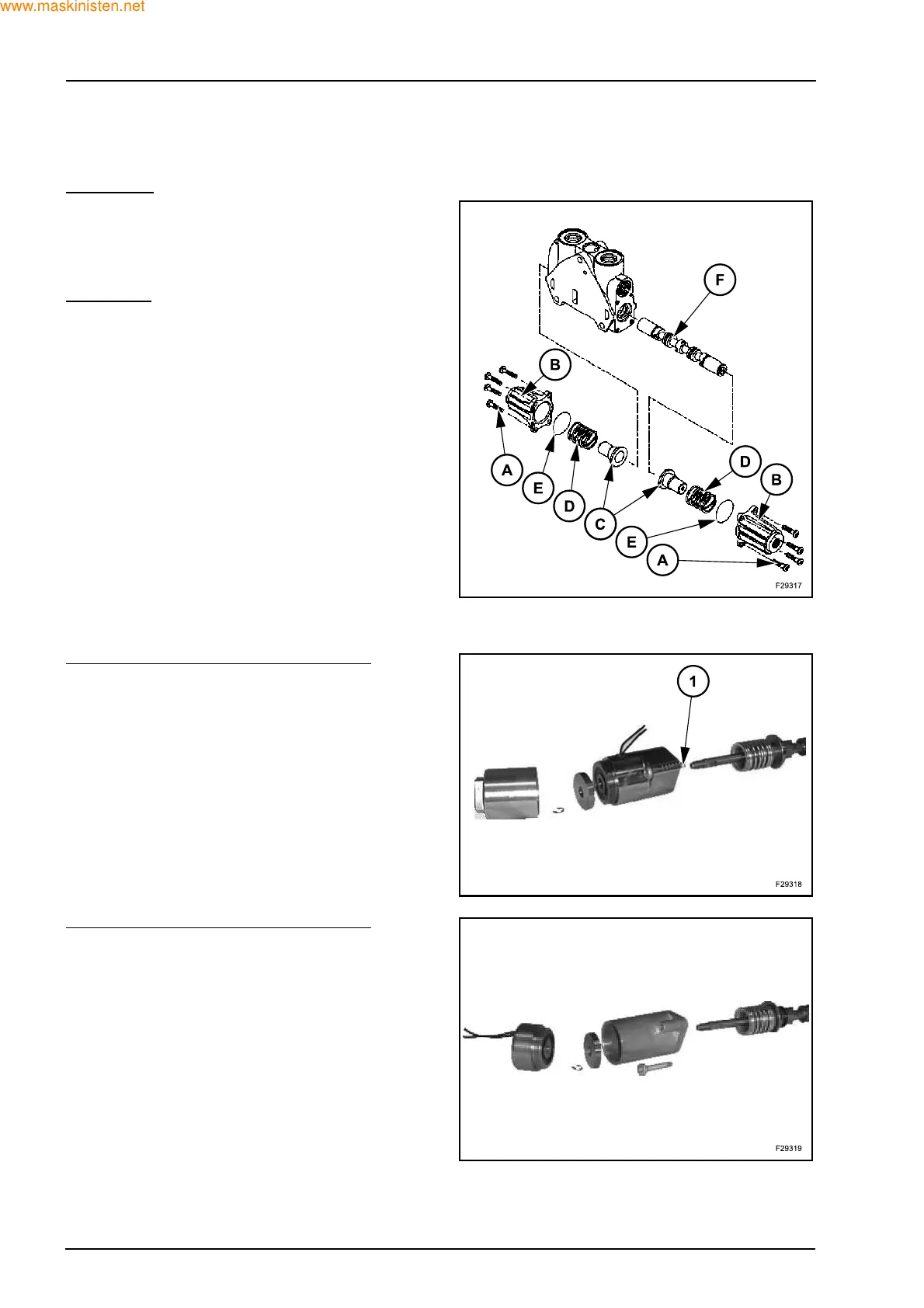
Disassembly and reassembly hydraulic control
spool
Disassembly
Z Remove the screws (A), and the plate (B).
Z Extract the spring guides (C) and the springs (D).
Z Discard the seals (E).
Z Remove the spool (F) from the valve section.
Reassembly
Z Grease and install the spool (F) in the valve sec-
tion.
Z Install the springs (D) in the caps (B).
Z Install the spring guides (C) in the springs (D).
Z Install new seals (E).
Z Install the cap assemblies on the valve section, in-
stall and tighten the screws (A) to a torque of 9 to
11 Nm.
Electrical detent system spool
Solenoid replacement (with spool pulled out)
Z Remove the 2 mounting screws (A) and the detent
system.
Z Unscrew the rear housing (B).
Z Remove the circlip (C), the spring and the coil.
Z Install a new solenoid (D).
Z Reassemble parts in reverse order.
Z Tightening torque:
screws (A) - 9 to 11 Nm
rear housing (B) - 1.8 to 2.2 Nm
Solenoid replacement (with spool pushed in)
Z Remove the solenoid (A).
Z Install a new solenoid.
Z Tightening torque - 18 to 22 Nm.