112 SECTION 55 - ELECTRICAL SYSTEM
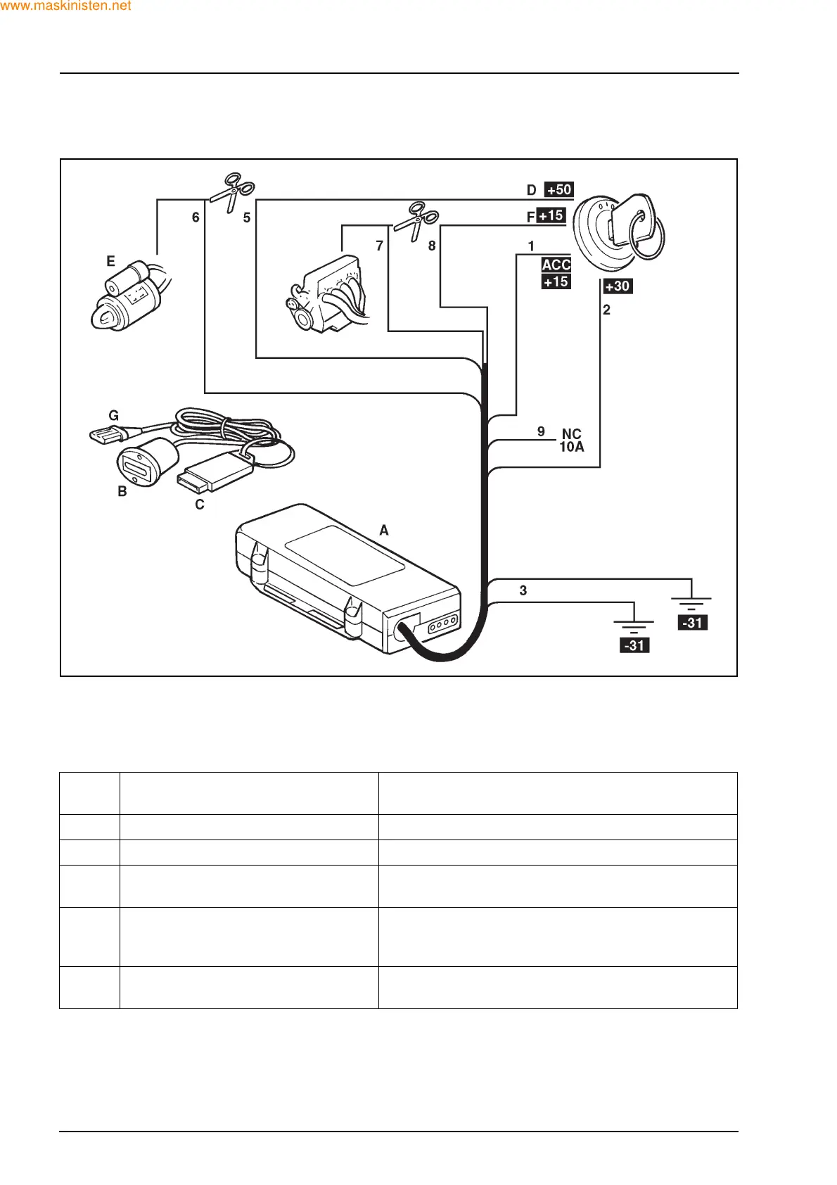
3.7 IMMOBILISER CIRCUIT
A. M38 Immobiliser
B. Electronic key socket with LED
C. 2 piece electronic key
D. + 50 to ignition
E. Starter motor
F. + 15 key positive
G. Electronic key
F28667
Wire
No.
Function Connection
1 (+15) Key positive Connected to the + 12 V full ignition supply
2 (+30) Permanent + 12 V power supply Connected to the wire from the battery positive
3 (-31) Negative power supply Connected to the vehicle negative at two independent
points
5 - 6 Immobilization relay No. 2 Connected in line with the wire controlling the starter
motor relay/solenoid - Minimum 500 mA maximum 10 A
capacity
7 - 8 - 9 Immobilization relay No. 1 Connect in line with the wire controlling the ignition or
fuel circuit - Minimum 500 mA maximum 10 A capacity
 Loading...


