116 SECTION 55 - ELECTRICAL SYSTEM
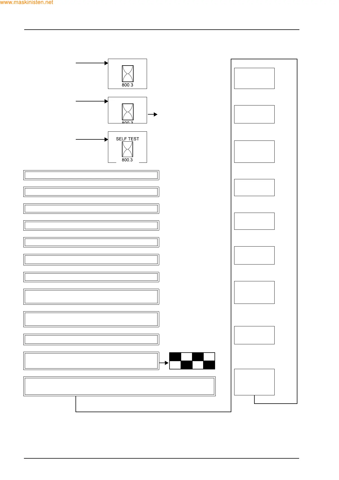
4.3 PROCEDURE ABOUT SELF TEST
Z
Power up LCD and show work
hours for 10 seconds
Any of the above at with ignition
low
Foot max: X.X.
Foot min: X.X.
113/111
range
Go to menu
Hand max: X.X.
Hand min: X.X.
125/120
range
Normal “Key ON”
Z
Z
Initiate Self test
Foot %: XXX
Hand %: XXX
113/122
range
Any of the above at “Key ON”
Check:
100 mA < Current draw < 1amp
Step 1: Lamps switch on at full intensity.
Requested en-
gine rpm: XXX
98/88
range
Step 2: Lamps switch off after 2 seconds.
10 mA < Current draw < 1 mA
Step 3: Wait 2 seconds.
Check:
100 mA < Current draw < 1 A
Fuel lvl: XX.X
Fuel tank: XX
117/120
range
Step 4: Instrument backlighting turns on at full intensity.
Step 5: Lamps switch off after 2 seconds.
10 mA < Current draw < 100 mA
Voltage: XX.X
Trans oil temp:
XX
116/124
range
Step 6: Wait 2 seconds.
Step 7: Sweep all 5 gauges to maximum angle.
Makes sure that needles can
move freely and have proper po-
sition
Brakes: XXX
Engine rpm:
XXXX
102/92
range
Step 8: 2 seconds after maximum angle sweep to red
border.
Makes sure that needles are
properly calibrated to applique
Step 9: 2 seconds after red-green border is reached move
to second red border for voltage.
Radiator water
temp. XXX
Air temp. XXX
107/123
range
Step 10: Park all gauges and start LCD test.
Step 11: When LCD test is complete sound alarm for 2
seconds.
Engine oil temp:
XXX
Fuel temp: XXX
122/126
range
Step 12: The following is shown on the LCD display until the key is turned to OFF or the
cycle ends. All gauges and lamps should work as normal and engine will be able to be
started.
$
 Loading...


