Theory of Operation
6. Theory of Operation
6.1 Overview
The 62000H Series DC Power Supply with Solar Array Simulation has a total of 18 circuit
boards in it: A, C, D, E, F, G, H, I, K, L, NO, R, S, U, Y, YE, YG, and Z.
A board is the auxiliary power.
C board is the output stage control circuits.
D board is the main digital control board.
E board is the EMI filter.
F board is the input stage primary side.
G board is the GPIB & Ethernet control board.
H board is the high voltage input rectifier.
I board is the adapter for System Bus and USB.
K board has 24 (4*6) keys and an LED.
L board is the low voltage input rectifier.
NO board is the output noise board.
O board is the output stage secondary side.
R board is the adapter for Remote sense and current sharing.
S board is the output stage secondary side snubber circuits.
U board provides serial/parallel communication for System Bus and external
RS232/RS485 and USB interfaces.
Y board is the converter for Ethernet and GPIB.
YE board is the Ethernet external board (option.)
YG board is the GPIB external board (option.)
Z board is the fan control circuits.
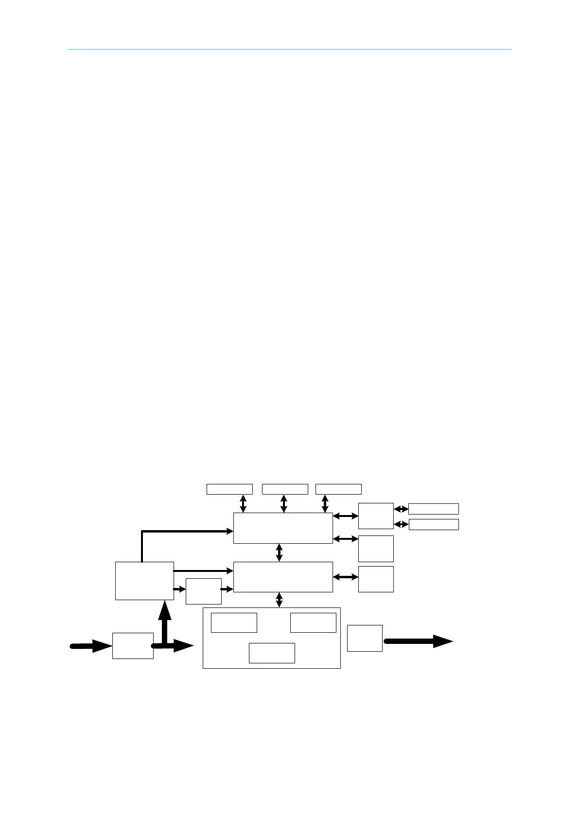
Figure 6-1 shows the system diagram.
Figure 6-1
INPUT
C Board
A Board
H/L Board
F Board
S Board
D Board
OUTPUT
K Board
U Board G Board
Y
Board
I
Board
R
Board
Z
Board
NO
Board
E Board
YE Board
YG Board
 Loading...
