Manual Operation
3.3.1 SYSTEM SETUP
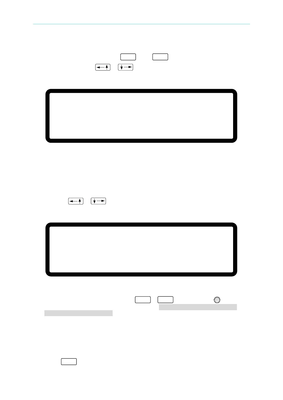
1. In the Config setup page, press “
” then “ ” to display the screen shown in
Figure 3-5. Use the “
”, “ ” keys to move the cursor to the desired
selection.
[
S Y S T E M S E T U P]
A P G V S E T
=
N O N E _
A P G I S E T
= N O N E
A P G V M E A S =
N O N E
A P G I M E A S
= N O N E
B U Z Z E R
= O N
P O W E R O N S T A T U S = D E F A U L T
Figure 3-5
3.3.1.1 APG
The Analog Programming interface (APG) performs the following two functions: 1. uses the
analog signal control panel to set the value and 2. uses the analog signal to indicate the panel
measurement. The values for set and measure can be set separately as described below.
1. Use the “
”, “ ” keys to move the cursor to the column to be set as shown in
Figure 3-6.
[S Y S T E M S E T U P
]
A P G V S E T
=
N O N E _
A P G I S E T
=
N O N E
A P G V M E A S =
N O N E
A P G I M E A S
= N O N E
B U Z Z E R
= O N
P O W E R O N S T A T U S =
D E F A U L T
Figure 3-6
2. For APG VSET, use the numeric keys - or the “Rotary” (
) knob to set
the mode. There are 5 selections for APG VSET: NONE / Vref(0-5V) /Vref(0-10V) /
Iref(4-20mA)/ Rref(0-5KOhm), where:
NONE: means not using the programming function.
Vref(0-5V): means using the external voltage source as the programming setting.
Vref(0-10V): means using the external voltage source as the programming setting.
Iref(4-20mA): means using the external voltage current source as the programming
setting.
Rref(0-5KOhm): means using the external resistance as the programming setting.
3. Press “ ” to confirm.
 Loading...
