Manual Operation
2. Use the numeric keys (
- ) or the “Rotary” ( ) knob to set the range of
SETTING MARGIN. The default is 3%.
3. Press “ ” to confirm.
4. Press “
” to return to the MAIN PAGE.
3.3.3 SERIES/PARALLEL
62000H Series DC Power Supplies with Solar Array Simulation may be connected in series or
parallel when in the CV/CC MODE. The maximum voltage is 1200V if connected in series and
the maximum current is 250A if connected in parallel. When the IV curve function is enabled
in the TABLE Mode, SAS Mode or IV PROGRAM Mode, only parallel connections are
supported (no series connections).
1. Series/Parallel cannot be used at the same time. A620028 and
A620027 models only support parallel connections.
2. The maximum output voltage or current is 1200V or 250A when
operating the 62000H Series with Solar Array Simulation in series or
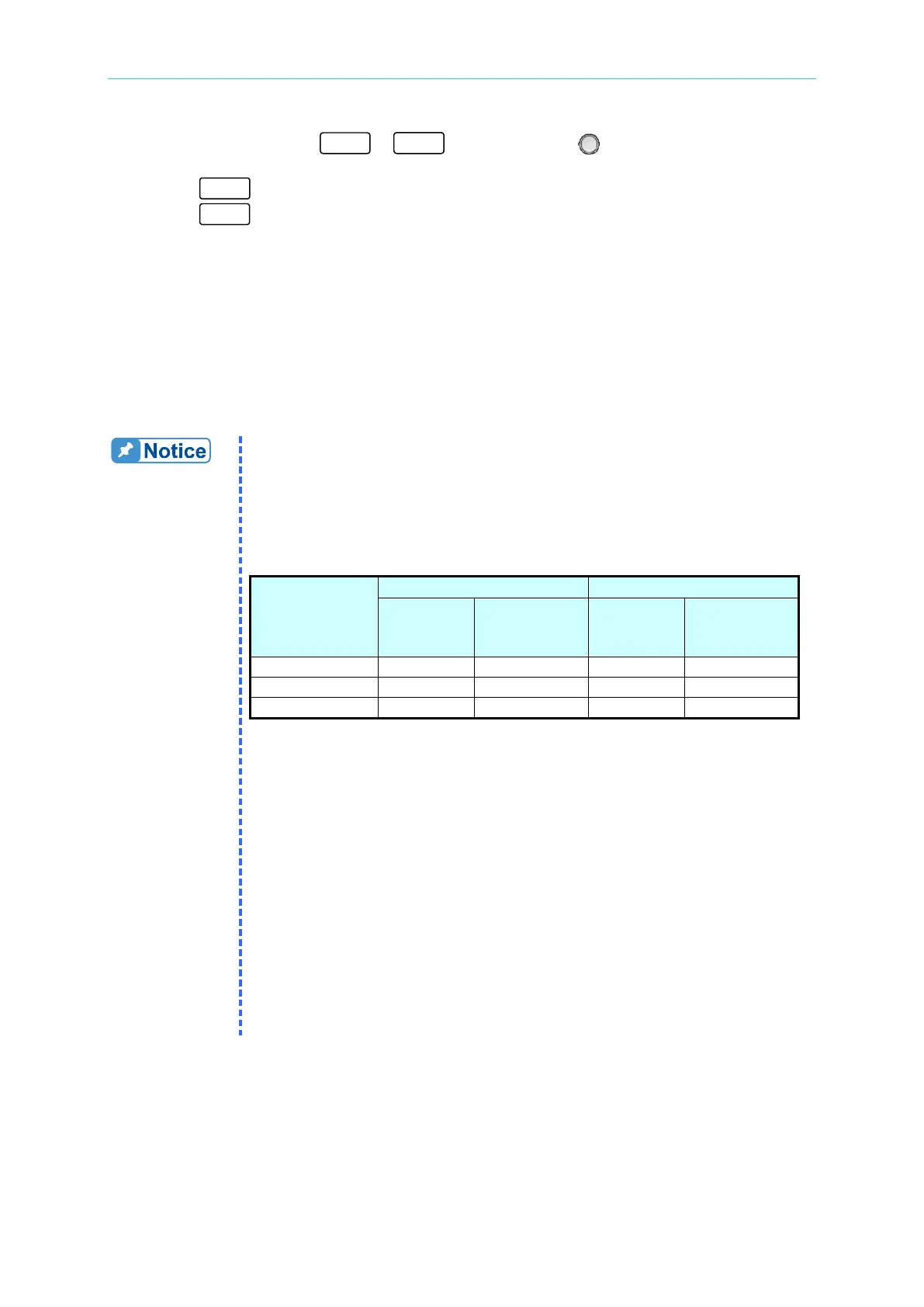
parallel. Table 3-1 shows the values for the 62xxxH-xxxS models.
Table 3-1
Model with
Solar Array
Max.
Devices
Max. Output
Voltage (V)
Max.
Devices
Max. Output
Current (A)
3. Model types cannot be mixed when operating in Series/Parallel.
4. Insure the breaker capacity is sufficient and the earth grounding wire
is grounded to earth ground when connecting in series/parallel.
5. When more than 5 devices are to be paralleled, contact the Service
Center or CHROMA agent for connection instructions.
6. Stack the DC Power Supplies vertically for parallel connection. The
standard CURRENT SHARING cable cannot be used if the devices
are placed horizontally in the parallel configuration; an optional
CURRENT SHARING (100CM) cable is required. Contact the
CHROMA Service Center or local agent for further information. No
more than 2 units may be paralleled when placed horizontally. .
7. Firmware versions 2.00 and above are not backward compatible.
Be sure to upgrade the firmware version from 1.XX to 2.00 when
connecting to a device with firmware version 2.00 for series use.
Contact Chroma’s service unit for a firmware upgrade.
 Loading...
