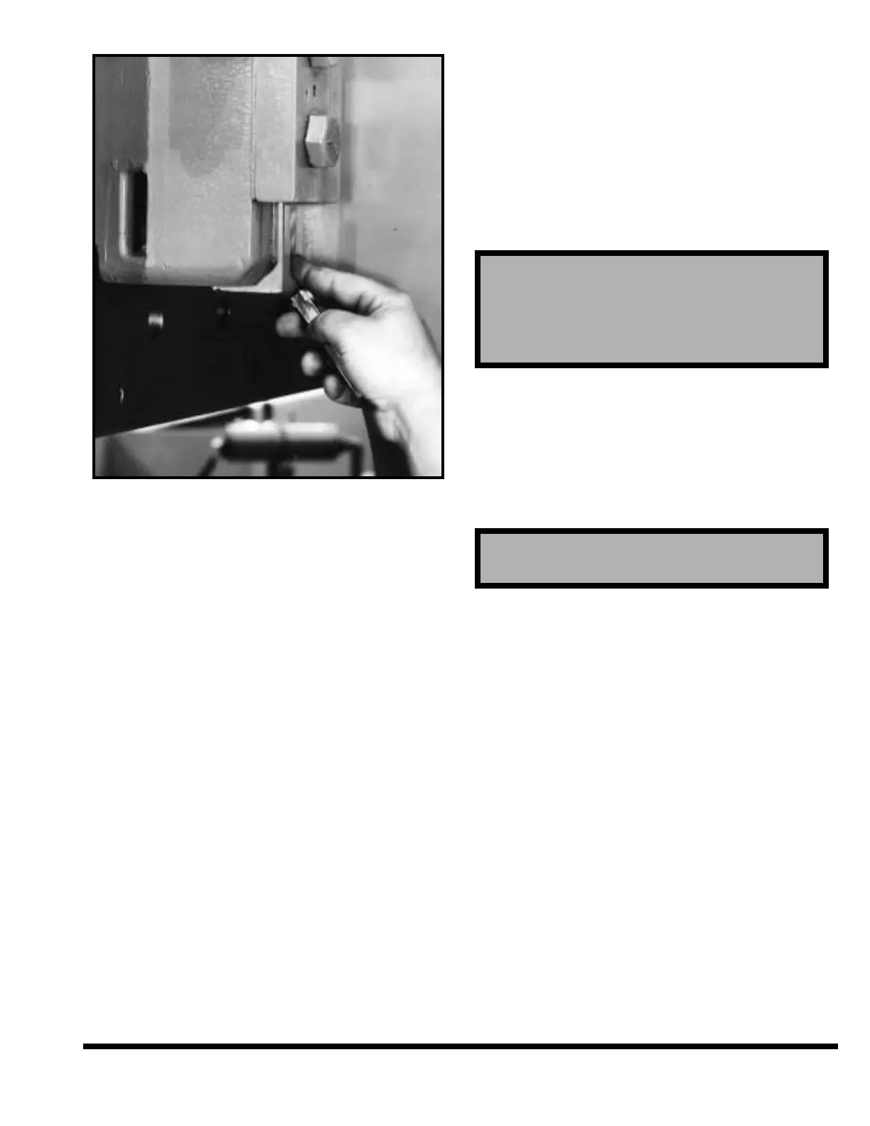
FIGURE 2-7 – Checking slide clearance
Regardless of level of the bed, if this condition is not
corrected the slides may score. Raise or lower the
rear of either housing to relieve twist in machine.
Some clearance must appear at the points which
have been tight.
These slide clearances are considered to be
the final and most important check on the
level of the machine since they are actual
running clearances.
After the machine is level, retighten foundation bolt
nuts securely. Recheck slide clearances. Do not
remove shims. Alignment may not be permanent,
recheck level in a few weeks. Do not use any grout-
ing around the machine. Leave the bed pit empty
and cover with steel plate.
HYDRAULIC RESERVOIR
Remove pipe plug from auxiliary cover plate and
install the air breather. Remove shipping caps and
install filler / breathers.
The hydraulic reservoirs are equipped with a drain
valve. See Figure 1-2. Before starting machine,
crack this valve open. Water may have collected in
the tank during shipment. If no water comes out, or
when oil starts coming out, close the valve secure-
ly. Repeat this check monthly.
LUBRICATION
Proper lubrication is of extreme importance to your
machine. The following lubrication points should
be checked before start-up and at regular intervals
thereafter.
1. Hydraulic Reservoir: Before starting machine
check for proper fluid level at the oil sight gage.
See Figure 1-2. Fluid level must be checked
with the ram at the top of the stroke.
2. Cylinder Clevis Pins: Lubricate while cycling ram
under load, such as obtained with a bumping die.
Lubricate once a week for the first six weeks and
once a month thereafter. Use a #2 lithium base
grease with “moly” additive (C.I. grease H-2M).
This must be done after electrical connections
are made and the machine is running.
3. Ram Slides: The ram slides (Figure 1-1) are
automatically lubricated with clean, filtered oil
from the hydraulic system. When stroking the
ram, oil is forced through metering fittings on
each ram guide. Before starting the press
brake, the exposed part of guides should be
wiped clean and oiled.
ELECTRICAL CONNECTION
Suitable electrical leads must be brought to the
machine as shown on certified Foundation Plan
drawing. These leads are connected to incoming
side of electrical disconnect switch in main electri-
cal enclosure. Be certain that leads are of sufficient
capacity and that proper voltage is fed to the
machine. CINCINNATI INCORPORATED equipment
requires that the incoming line supply at the
machine does not vary more than plus or minus
10% from the nominal. Some installations may
require additional line conditioning, other than
supplied with the machine controls. Contact
CINCINNATI INCORPORATED Service Department
for further information.
CAUTION
Keep clear of the moving ram.
CAUTION
Standard machines are designed for and
shipped with petroleum-based hydraulic
fluid, which is flammable. Check applicable
fire codes for special precautions.
2-7