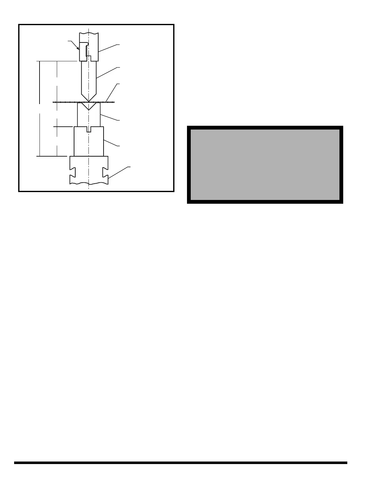
FIGURE 7-3 – Top of Material
Valid Range: Closed height of machine - Open
height of machine
Entry Format: XX.XXX English or XXX.XX Metric
Default Value: Open Height of machine
Note: If the TOP OF MATERIAL value is entered,
the following values will be changed auto-
matically if they are still at the default
value.
1. CLAMP POSITION - Change to TOP OF MATE-
RIAL - 0.01”
2. SPEED CHANGE - Change to TOP OF MATE-
RIAL + 0.25”
3. GUARD MUTE POSITION - Change to TOP OF
MATERIAL + 0.25”
These values are calculated as a convenience to
the operator and can be changed without affect-
ing the angle mode calculations.
CLAMP POS: This value is defined as the ram
position at which the workpiece is clamped
between the upper and lower dies. Default clamp
position value is the Closed Height of the
machine. This value may also be entered by first
positioning the ram to the desired clamp position
in SETUP mode and using the TRN key to trans-
fer the actual ram position value into this field.
Note the ram does not stop at the clamp position
unless the CLAMP function is set to ON or PAUSE
in Program Data for the step.
Valid Range: Closed Height - Open Height
Entry Format: XX.XXX English or XXX.XX Metric
Default Value: Closed Height
MUTE POS: (Optional: This field only appears if
a Presence Sensing Device is installed). This value
is defined as the position in the down stroke at
which the output of the light guard becomes
muted for the remainder of the stroke. If the light
guard beam is broken above the mute position,
the ram will stop. Once the ram is below the mute
position, interrupting the light curtain no longer
stops the ram.
Valid Range: Closed Height - Open Height
Entry Format: XX.XXX English or XXX.XX Metric
Default Value: Closed Height
UPPER DIE: An upper tool name can be entered
here for the program. It may contain up to eight
characters. This name is only used as a reference.
LOWER DIE: A lower tool name can be entered
here for the program. It may contain up to eight
characters. This name is only used as a reference.
After entering this last field or advancing past the
field with the down field key, the control will auto-
matically go to the PROGRAM DATA screen if the
ENTER NEW PROGRAM function was used. Oth-
erwise the highlighted field will remain as is.
RAM UP SPEED: This parameter selects the
speed of the ram as it moves up after reversal.
The speed can be set to HIGH, MEDIUM or LOW.
The ram will move up in the programmed speed
until the speed change position is reached. Once
above the speed change point, the ram will move
up in HIGH speed. Select the desired speed using
the softkey buttons.
PROGRAM DATA
Shown next is the PROGRAM DATA screen. Note
the values shown on the screen are the default val-
ues which will be set if the ENTER NEW PROG
function was pressed, otherwise the values dis-
played will be from the current program. This
screen is shown with ANGLE MODE selected ON.
! ! ! DANGER !
! ! ! DANGER !
!
!
!
!
THE MUTE POSITION MUST BE SET AT A
POINT WHERE THE SPACE OR OPENING
BETWEEN THE DIES AND MATERIAL IS LESS
THAN 1/4”. IF IT IS NOT, OPERATING PERSON-
NEL WILL NOT BE PROPERLY PROTECTED BY
THE PRESENCE SENSING SAFEGUARDING
DEVICE AND COULD BE SERIOUSLY INJURED.