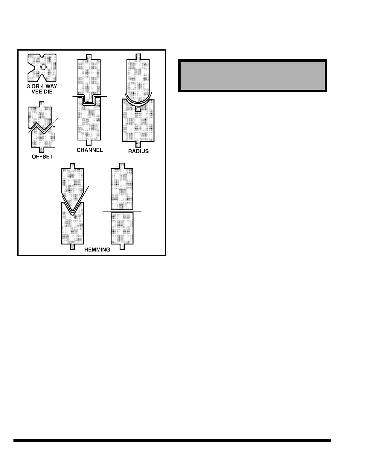
CINCINNATI INCORPORATED can provide many
other types of standard and special dies, some of
which are shown in Figure 5-4.
FIGURE 5-4 – Types of dies
DIE SETS: Special care and precautions should be
taken when operating die sets with guide pins
and bushings.
Depending on the working height of the die set,
the full stroke return may cause the die set
guide pins and bushings to separate. Re-entry of
the guide pins into the bushings may be difficult,
if not impossible. Each die set application should
be reviewed for this condition.
CINCINNATI INCORPORATED recommends that
the working height of all die sets be such that the
bushings never leave the guide pins when the
ram makes a full up stroke.
TOOL INSTALLATION
To install the tooling, use the following procedure:
✦ Turn “ON” the main disconnect switch.
✦ Depress MAIN DRIVE - START pushbutton on
FM Control Station (Figure 6-1).
✦ Turn OPERATOR CONTROL selector to “ON”
position.
✦ Use MODE SELECT to place machine in “SET-
UP” mode.
SETUP mode is used to run the ram down
using the Palmbutton Operator Station, and
up using the RAM UP button. This mode is to
be used only for positioning the ram under no-
load conditions.
✦ If the ram is not at maximum “up” position,
depress RAM UP button on Palmbutton Opera-
tor Station to raise ram. Ram will move to the
maximum “up” position and stop. When the
ram stops, continue with the next step.
✦ Turn the OPERATOR CONTROLS selector on
the FM Control Station to “OFF” position and
remove the key to prevent ram movement.
✦ If the filler block has not already been installed,
deburr, clean and lightly oil bed top. Place nuts
for filler block screws in proper bed cross slots.
Place filler block (die holder) on bed and lightly
bolt in place. At this time, also install optional
die aligners (3 front and 3 back) to the front and
back of the bed. In some cases a filler block may
not be required and die may be placed directly
on the bed. Deburr, clean and lightly oil the top
of filler block. Loosen all of the filler block set
screws.
✦ Measure the height of the lower die and upper
die together. Turn the Operator Controls Selec-
tor on the FM Control Station to “ON”. Lower
the ram to a height above the filler block equal
to the die height plus 1/4”. Turn the Operator
Controls Selector to “OFF” and remove key.
✦ Insert lower die on the filler block. Leave it
extended past end of bed several inches. Visu-
ally center filler block so lower die is aligned
with slot in the ram nose.
✦ Loosen all ram die clamp nuts about .125”
(3.2mm).
✦ Rest the upper die on extended portion of lower
die. Make sure tongue of upper die is in the ram
nose slot and that the upper die is trapped by
the lower die and ram die slot. See Figure 5-5.
Then slide upper die into lengthwise position
with the lower die. Slide the set of dies into a
centered position on the machine.
CAUTION
Before proceeding, read guidelines in SAFETY
Section for installing tooling.
5-2